A diode is a two-terminal component that only allows electrical current to flow in one direction. It is also referred to as a rectifier, as it converts alternating current (AC) into direct current (DC). Since diodes function like "one-way gates," it's crucial to know how to identify their polarity. Usually, you can determine this by looking at the markings, but if they are worn off or missing, a multimeter can come in handy.
Checking the Markings
Step 1. Understand how a diode works.
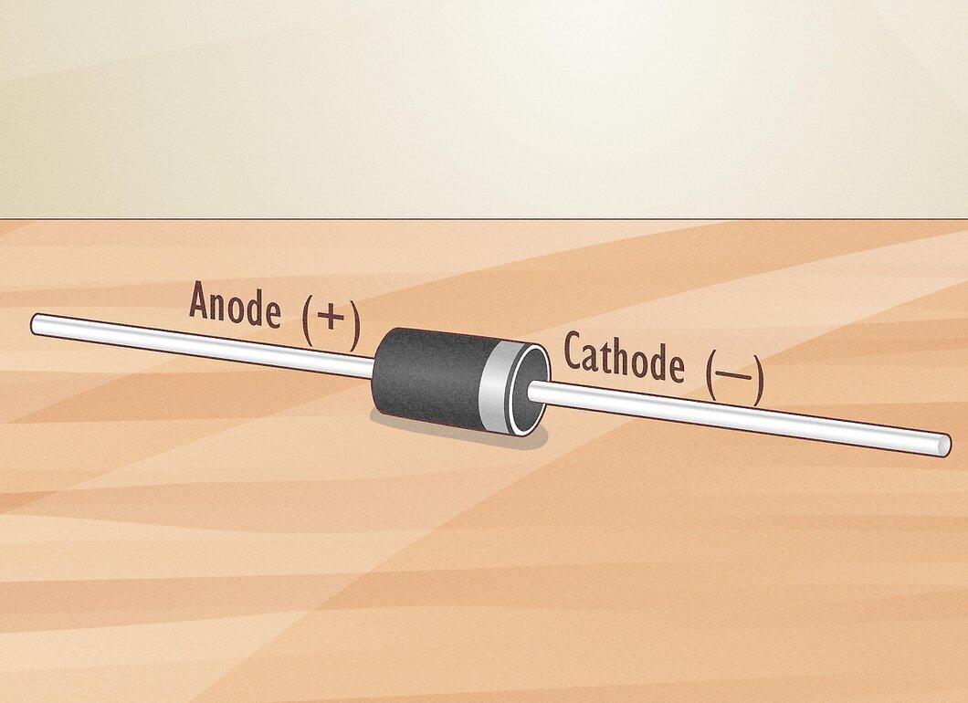
Familiarize yourself with the working principle of a diode. It consists of p-type and n-type semiconductors. The n-type semiconductor represents the negative side of the diode—the cathode—while the p-type represents the positive side, or anode.
- If the positive terminal of a voltage source is connected to the anode and the negative to the cathode, the diode will start conducting current.
- If the diode is connected in reverse, it will block current (up to a certain threshold).
Step 2. Learn the symbols.
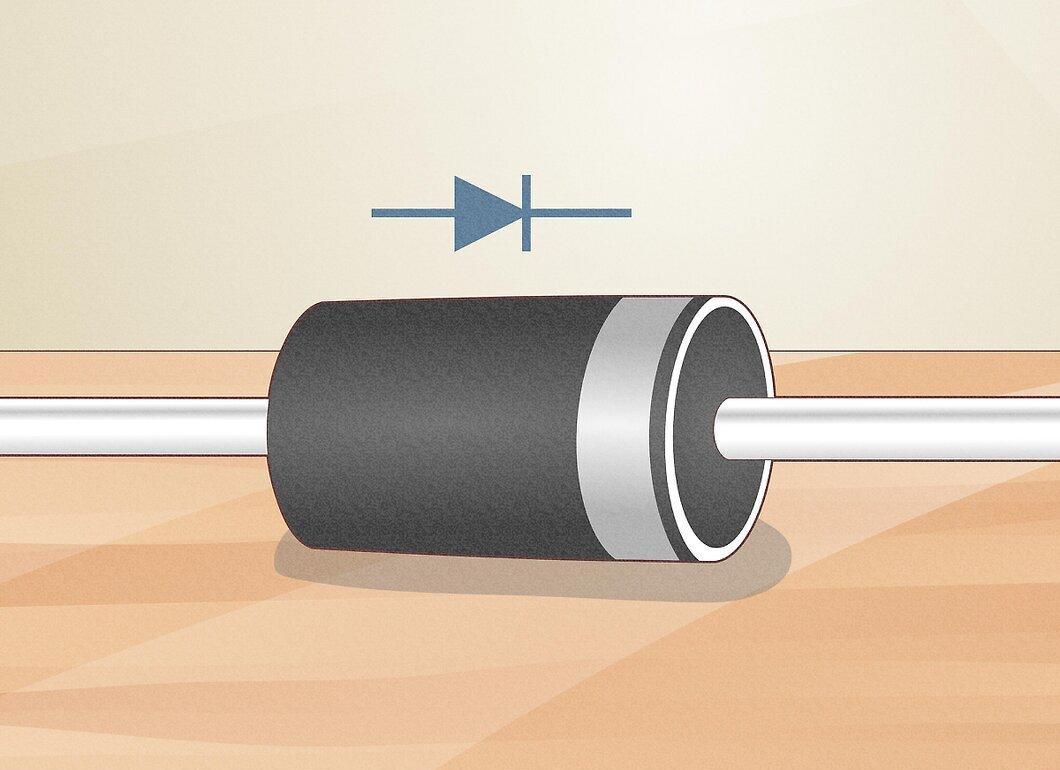
Understand what the diagrams represent. Diodes are represented by the symbol (—▷|—), which indicates how they should be installed. The arrow points to the positive side, while the vertical line indicates the negative side.
- The arrow points to the positive side, while the vertical line indicates the negative. You can remember this: the positive side "transitions" into the negative, and the arrow shows the direction of flow.
Step 3. Look for a colored band.
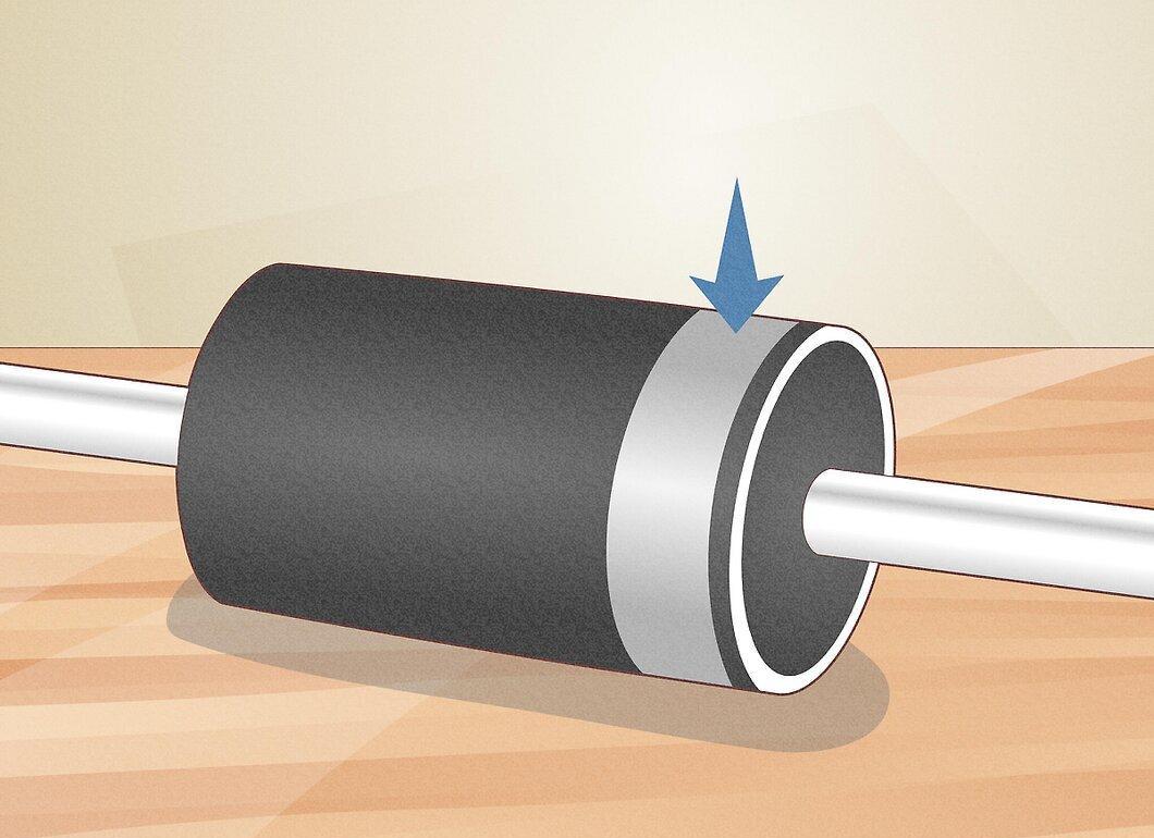
If there are no markings on the diode, check for a ring, band, or line. Typically, a large colored band is located near the negative side (cathode) of most diodes.
Step 4. Identify the anode of the LED.
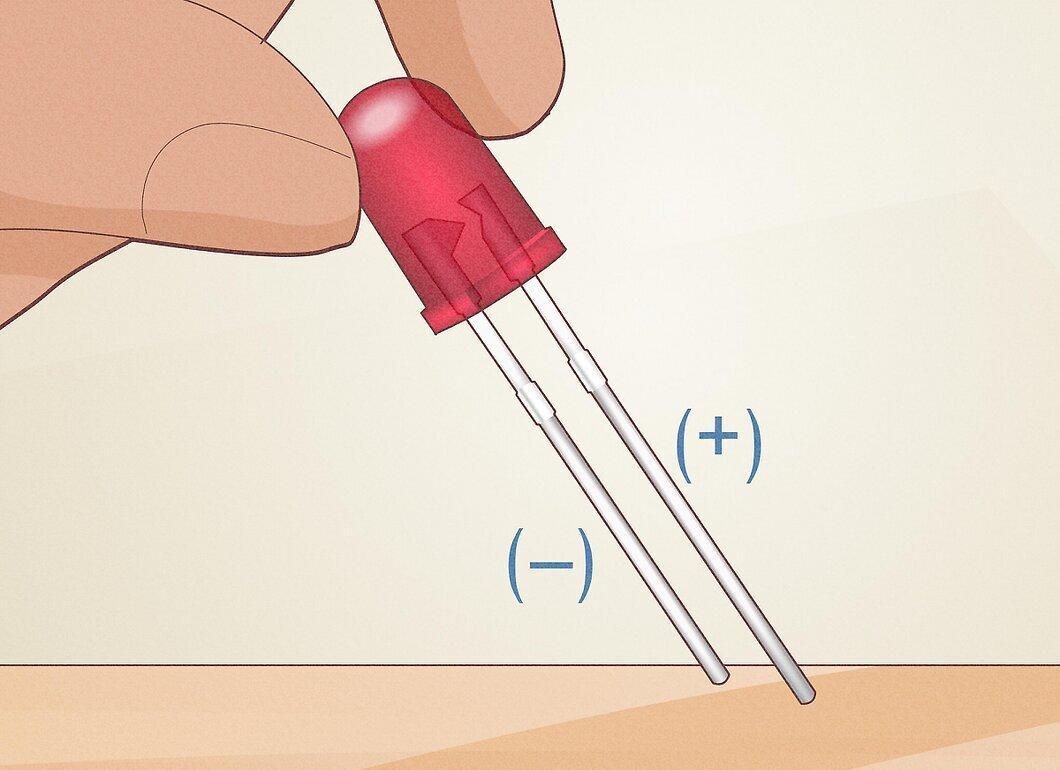
Determine which leg of the LED is positive. The longer leg will be the anode.
- If the legs have been trimmed, look at the body of the LED. The electrode closer to the flat edge is the cathode.
Using a Multimeter
Step 1. Set the multimeter to diode testing mode.
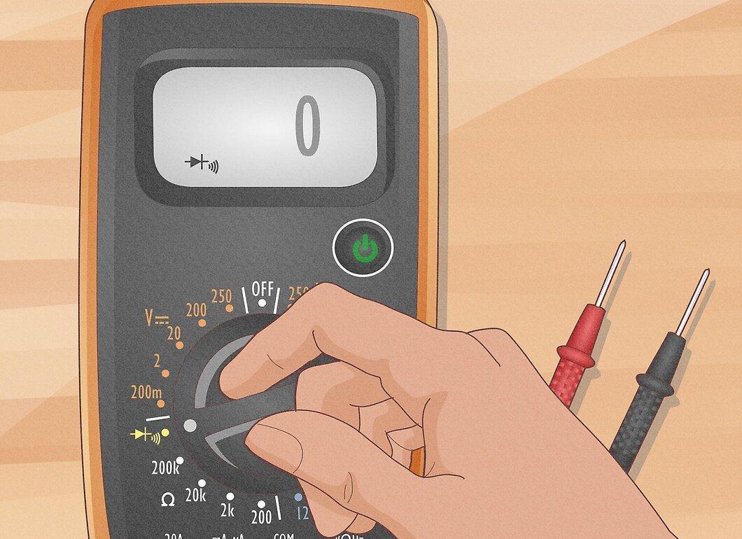
Configure the multimeter to diode testing mode. Rotate the dial to the diode symbol (—▷|—). In this mode, the multimeter will allow a small current to pass through the diode for checking.
- You can also test the diode by setting the multimeter to resistance measurement mode (Ω).
Step 2. Connect the multimeter to the diode.
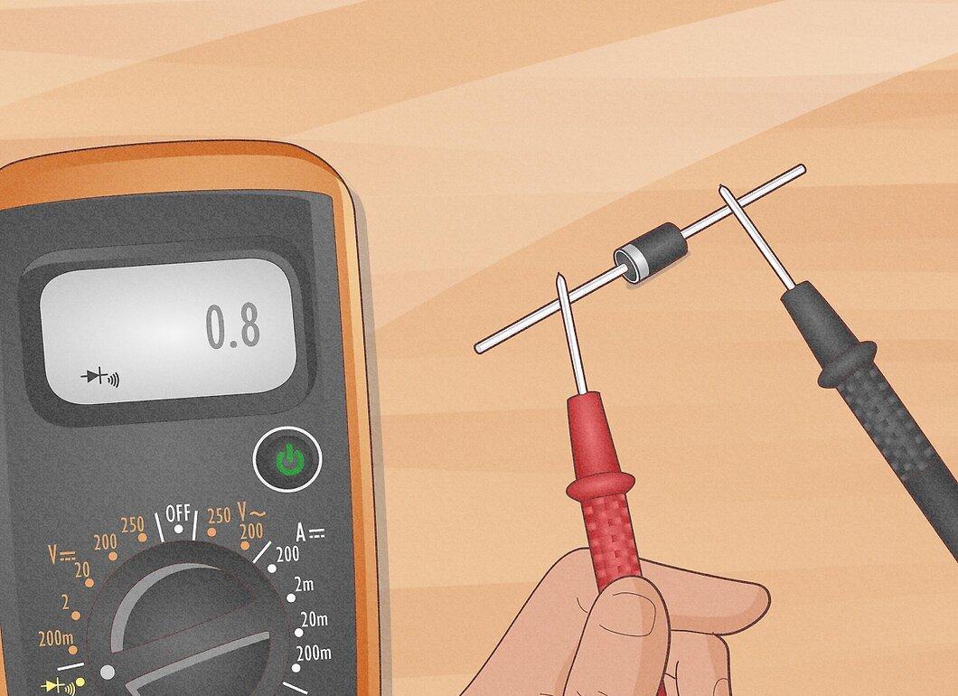
Connect the multimeter to the diode. Attach the positive probe to one end of the diode and the negative probe to the other. The display will show readings.
- If the multimeter is in diode testing mode and the probes are connected correctly (positive to positive, negative to negative), the screen will display a voltage. If the connections are incorrect, you will see nothing.
- If there is no diode testing mode and the probes are connected correctly, the display will show low resistance. Otherwise, a high resistance message, indicated as "OL," may appear.
Step 3. Test the LED.
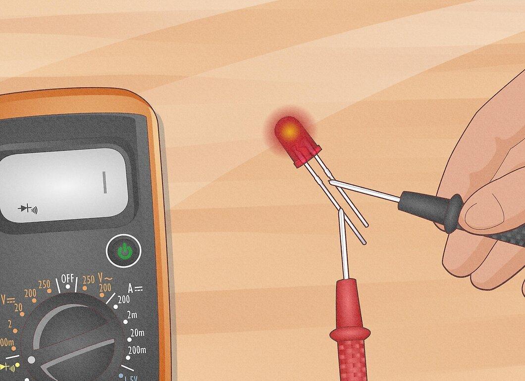
Check the functionality of the LED. Ensure the multimeter is set to diode testing mode. Connect the positive probe to one lead and the negative probe to the other. If the LED lights up, it means the positive probe is touching the anode and the negative probe is touching the cathode. If the LED does not light up, the probes are connected to the opposite ends.