A multimeter, also known as a voltmeter or VOM (commonly referred to as a tester in Russia), is a device that measures resistance, voltage, and current in electronic circuits. Some models can also test diodes and conductivity. Multimeters are small, lightweight, and battery-operated, capable of testing a wide range of electronic components in various situations, making them indispensable tools for anyone needing to check and repair electronic circuits.
Measuring Resistance
Step 1. Connect the multimeter to the circuit.
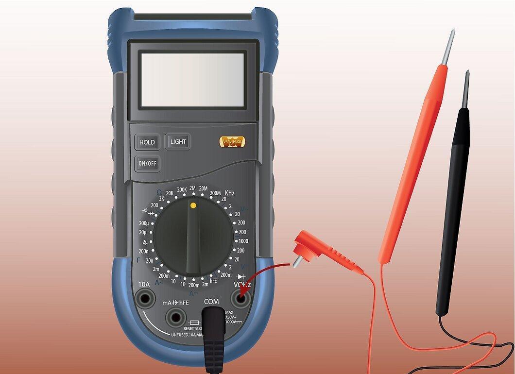
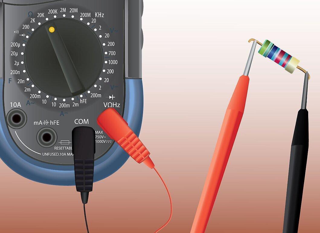
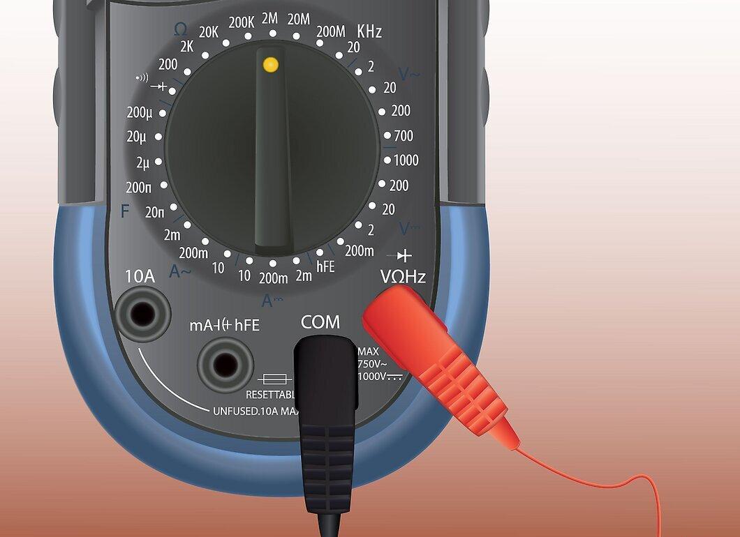
Connect the multimeter to the circuit. Insert the black probe into the common terminal and the red probe into the socket marked for measuring volts and ohms. The terminal may also be marked for diode testing.
Step 2. Turn the dial to set the multimeter for measuring resistance.
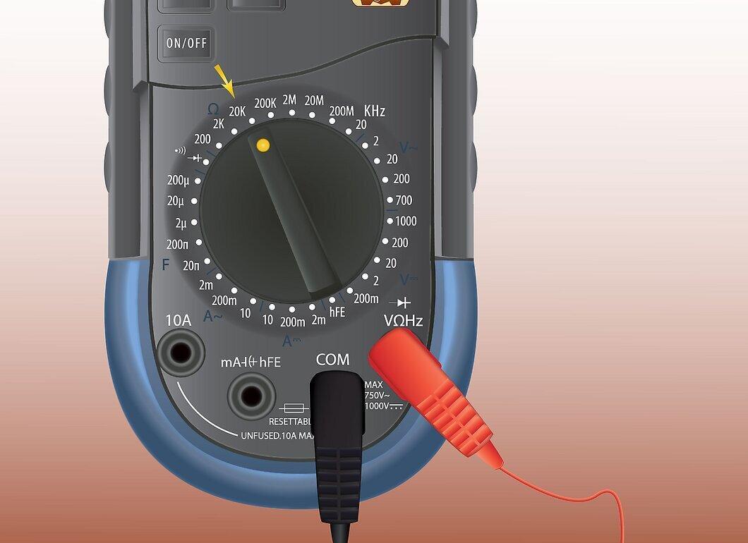
Turn the dial to set the multimeter for measuring resistance. This is often represented by the Greek letter omega (Ω), which denotes ohms, the unit of resistance.
Step 3. Disconnect power from the circuit.
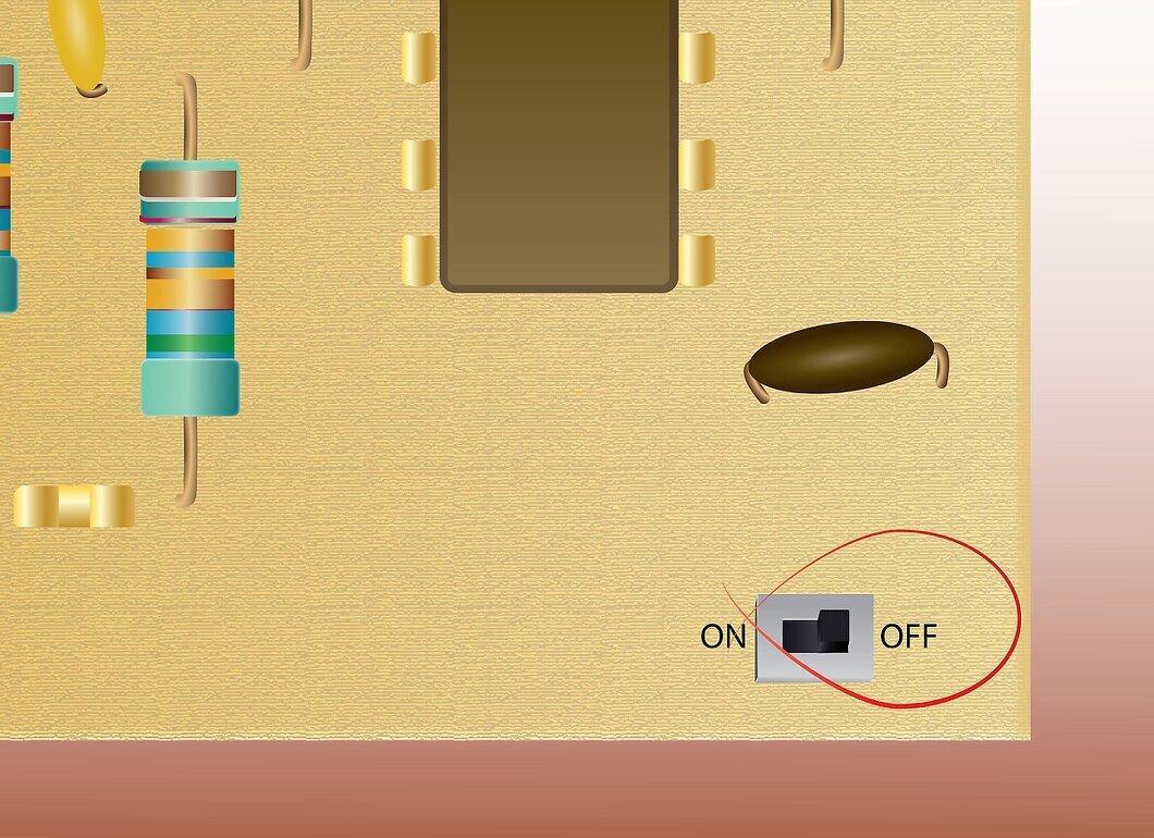
Step 4. Remove the resistor you wish to measure.
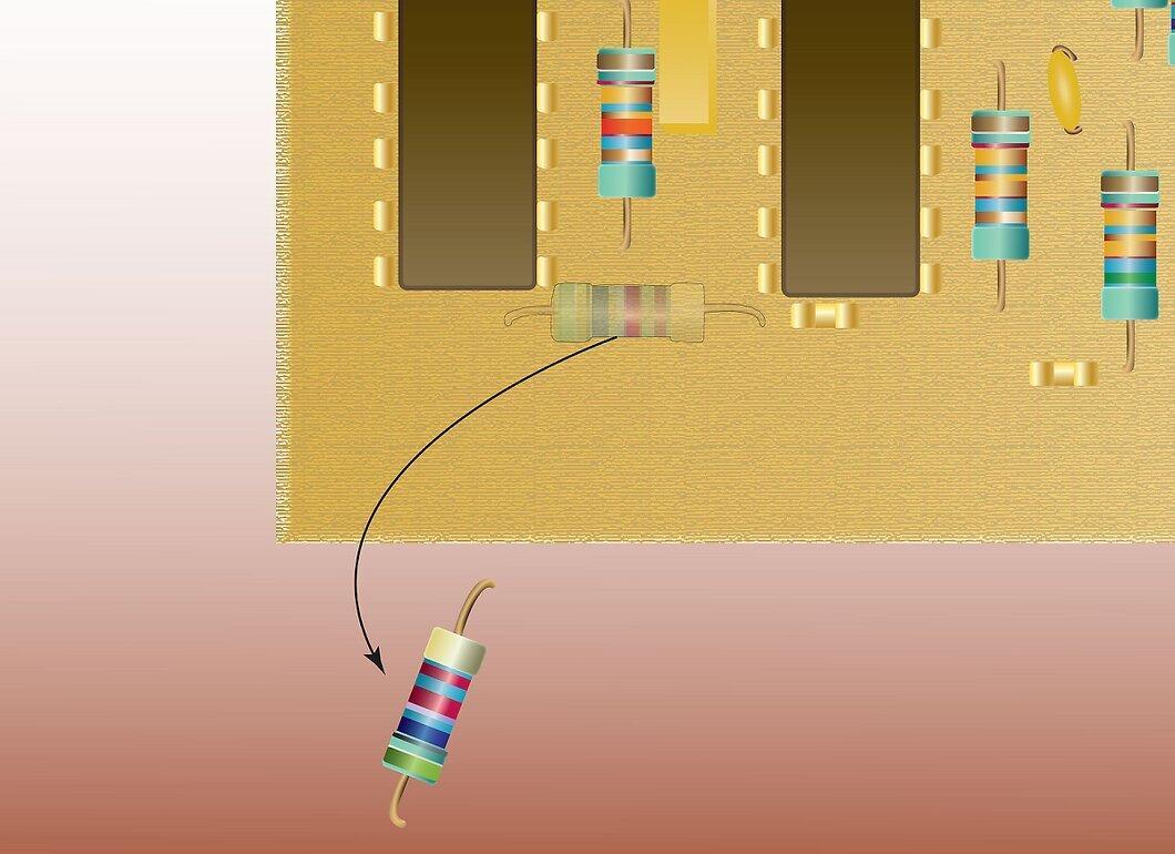
Remove the resistor you wish to measure. Leaving the resistor in the circuit may result in inaccurate readings.
Step 5. Touch the probes to each lead of the resistor.
Step 6. Read the display, noting the units of measurement.
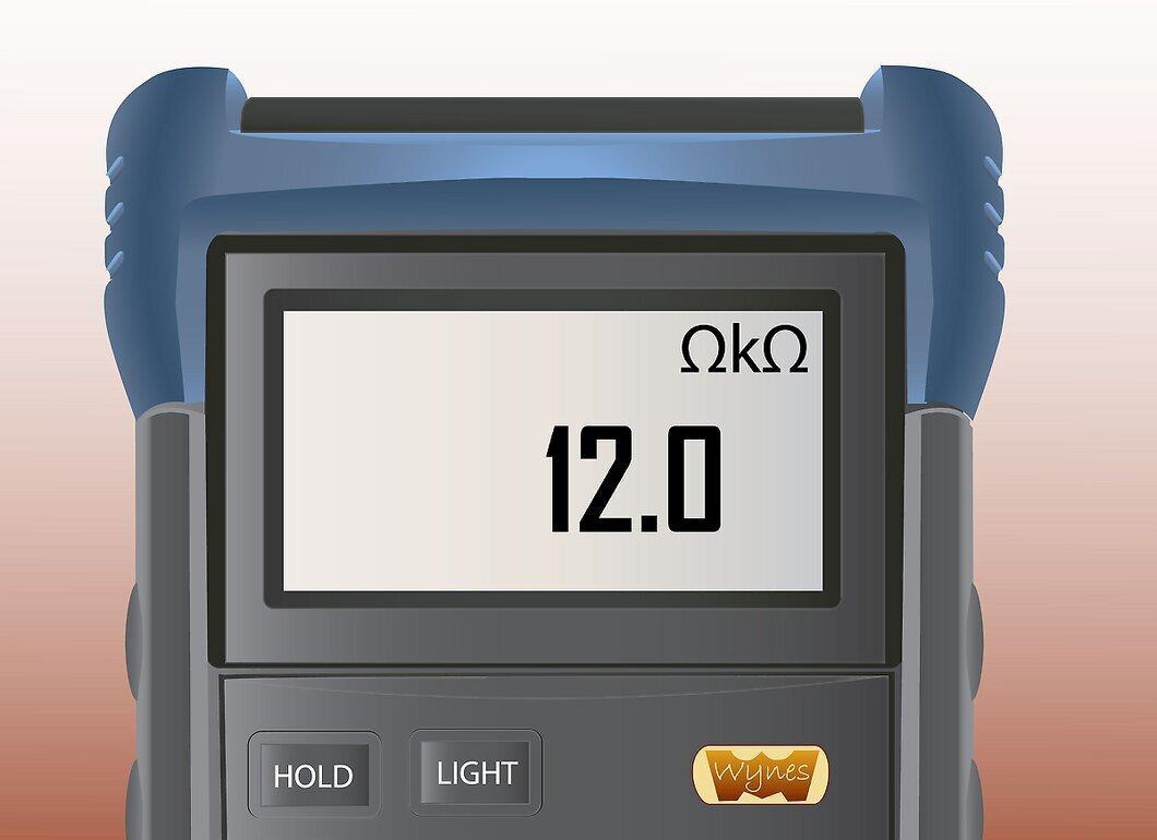
Read the display, noting the units of measurement. A reading of 10 could indicate 10 ohms, 10 kilo-ohms, or 10 mega-ohms.
Measuring Voltage
Step 1. Connect the multimeter to the circuit.
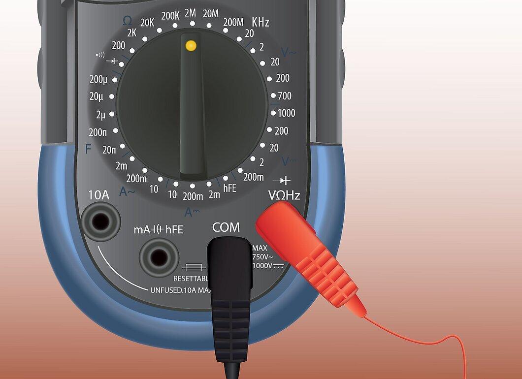
Connect the multimeter to the circuit. Insert the black probe into the common terminal and the red probe into the socket marked for measuring volts and ohms.
Step 2. Set the multimeter to the voltage you are measuring.
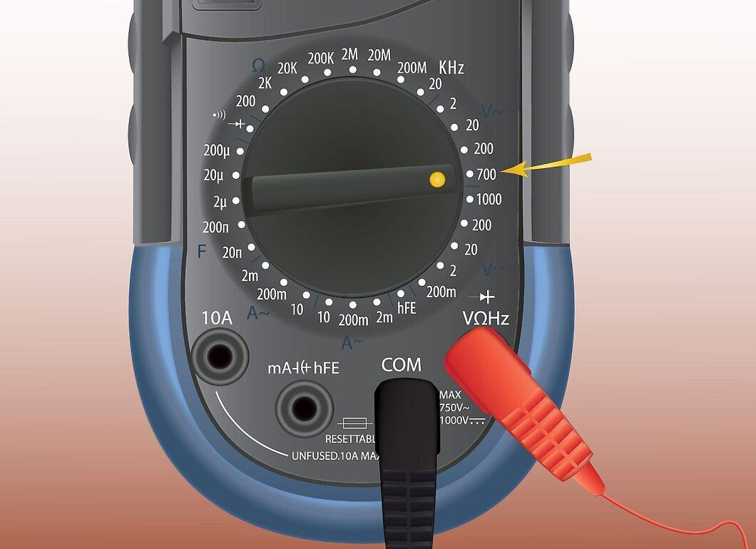
Set the multimeter to the voltage type you are measuring. You can measure DC voltage, millivolts DC, or AC volts. If your multimeter has an AutoRange feature, this is not necessary.
Step 3. Measure AC voltage by connecting to components.
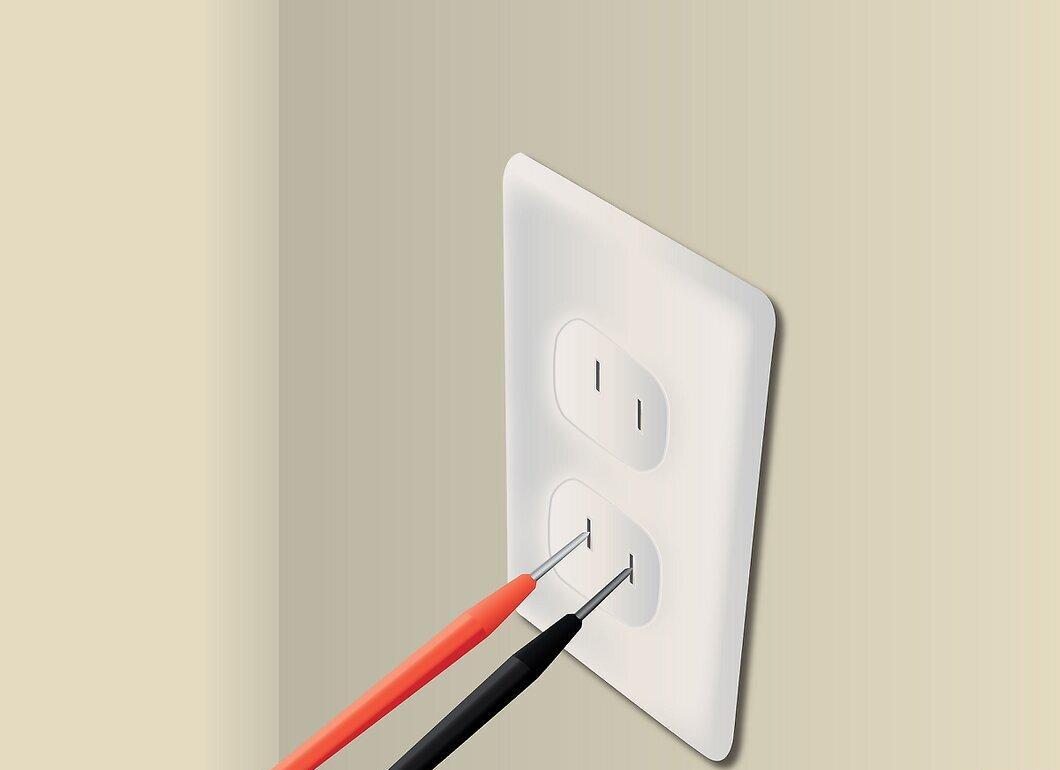
Measure AC voltage by connecting to the components. Polarity does not need to be observed.
Step 4. Observe polarity when measuring DC voltage or millivolts.
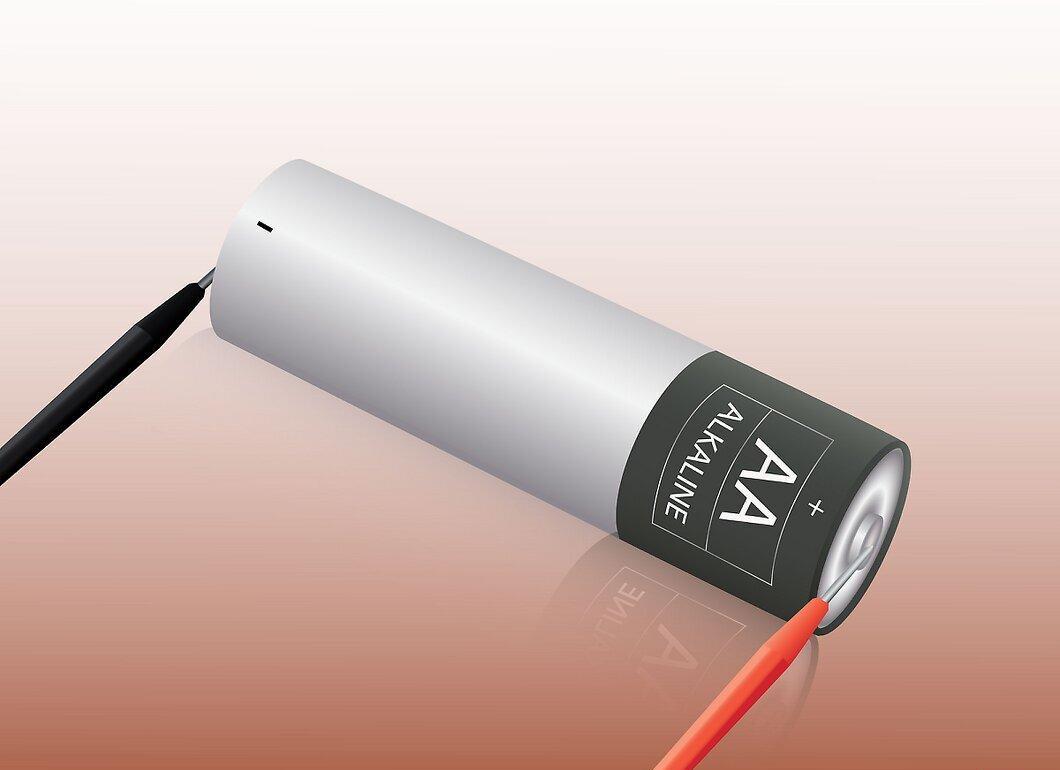
Observe polarity when measuring DC voltage or millivolts. Connect the black probe to the negative terminal of the component and the red probe to the positive terminal.
Step 5. Read the display, noting the units of measurement.
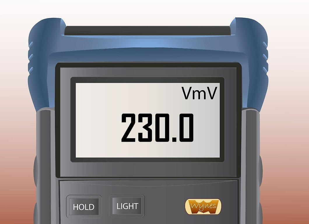
- If desired, you can use the hold function to retain the reading on the display after removing the probes. The multimeter will beep each time a different voltage is detected.
Measuring Current
Step 1. Select either the terminal marked for measuring 10 amps or the one labeled for measuring 300 milliamps.
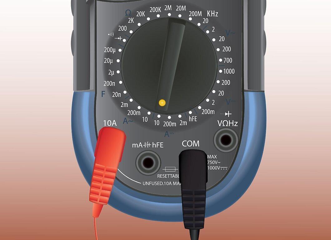
Select either the terminal marked for measuring 10 amps or the one labeled for measuring 300 milliamps. If you are unsure about the current strength, start with the 10 amp terminal until you are confident the current is less than 300 mA.
Step 2. Set the multimeter to measure current.
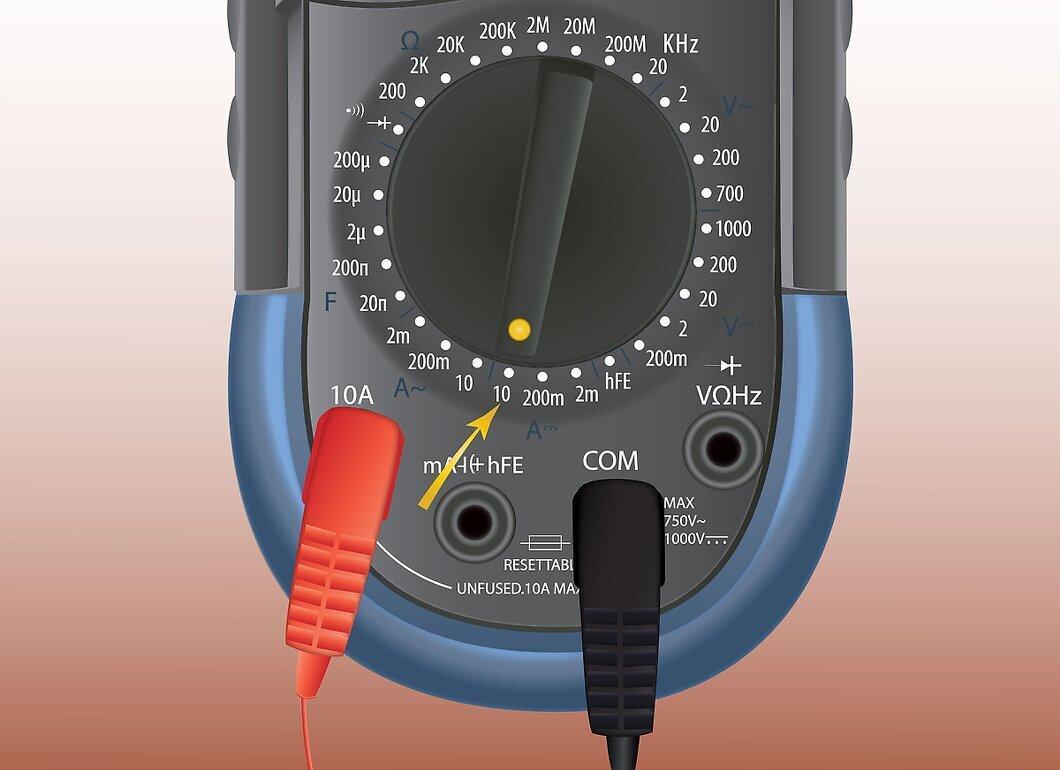
Set the multimeter to measure current. This may be indicated by the letter A.
Step 3. Disconnect power from the circuit.
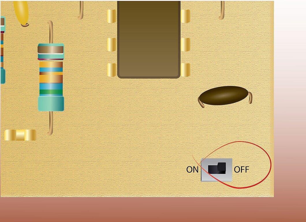
Step 4. Break the circuit.
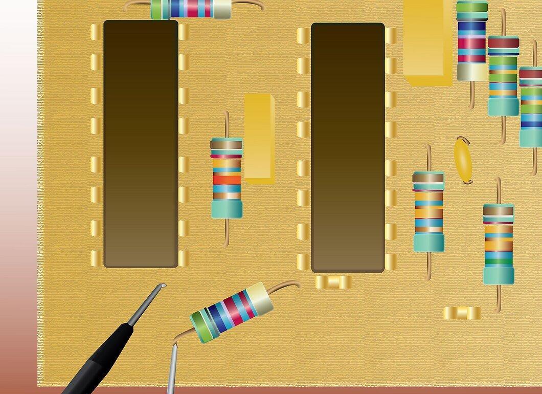
Break the circuit. To measure current, the multimeter must be placed in series with the circuit. (Black probe on the negative side, red probe on the positive side) Place the probes on either side of the break, respecting polarity.
Step 5. Turn the power back on.
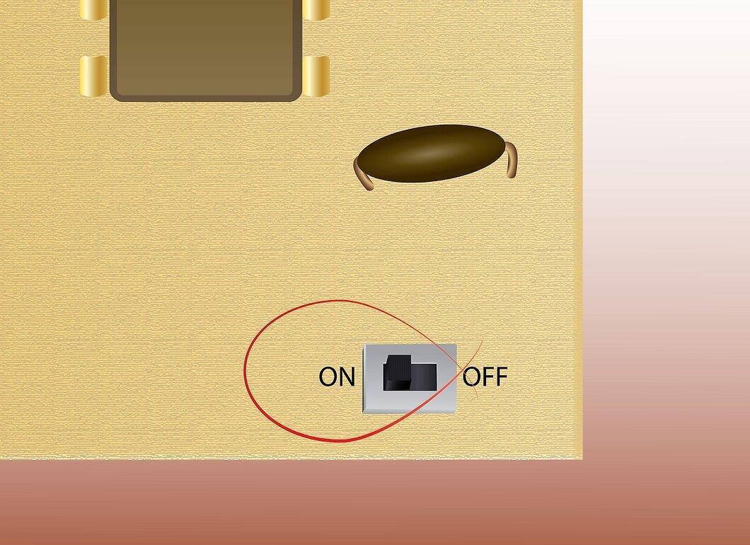
Turn the power back on. Current will flow through the circuit, into the red probe and through the multimeter, out of the black probe and back into the circuit.
Step 6. Read the display, remembering whether you are measuring amps or milliamps.
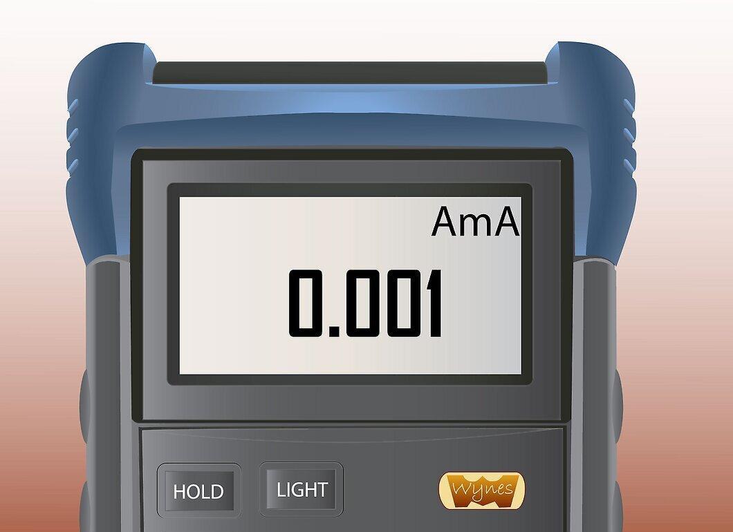
Read the display, keeping in mind whether you are measuring amps or milliamps. You can choose to use the hold function if desired.
Testing Diodes
Step 1. Insert the black probe into the common jack and the red probe into the terminal for measuring ohms, volts, or testing diodes.
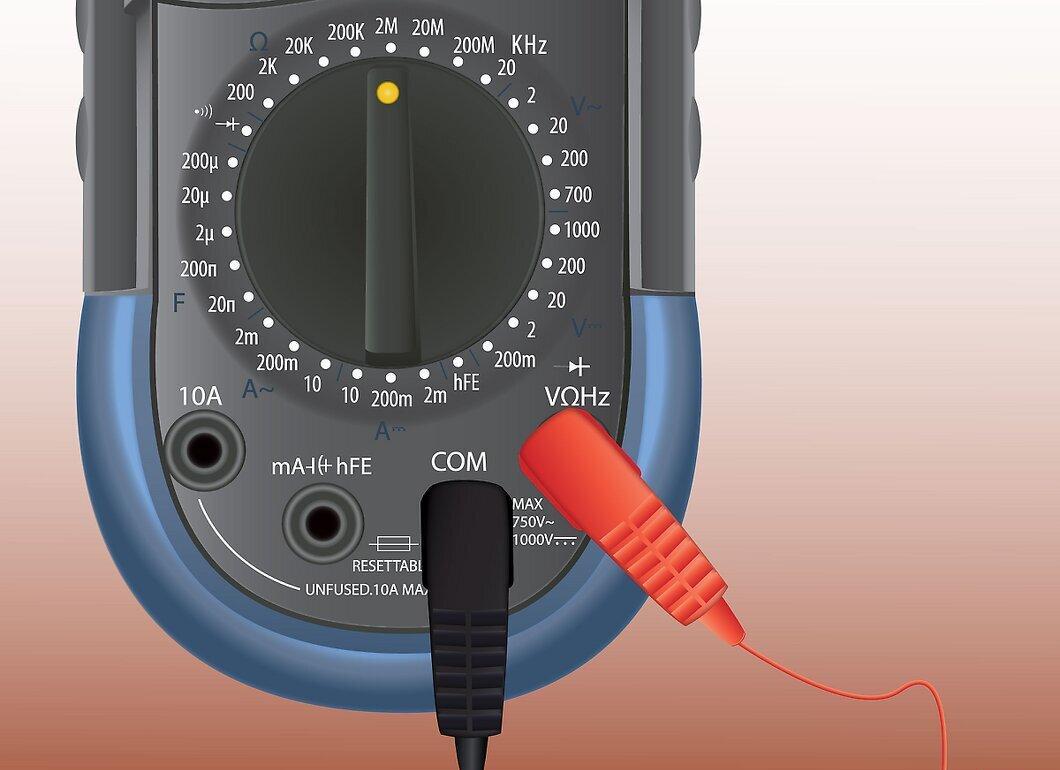
Step 2. Use the dial to select the diode testing function.
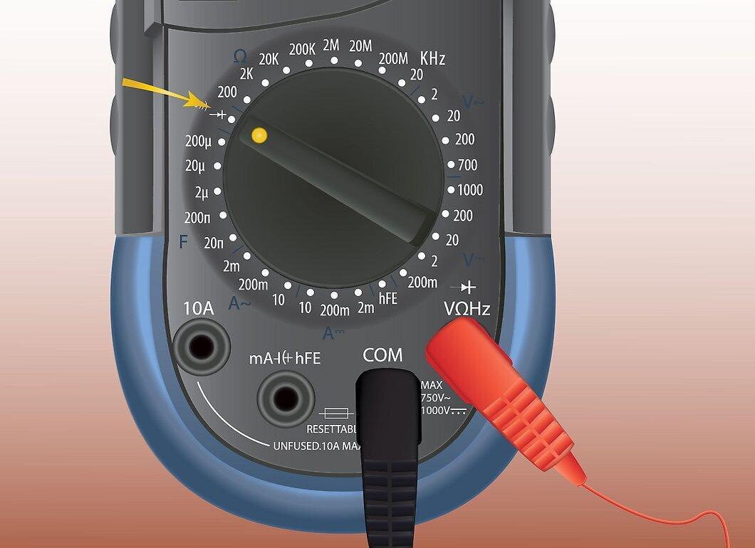
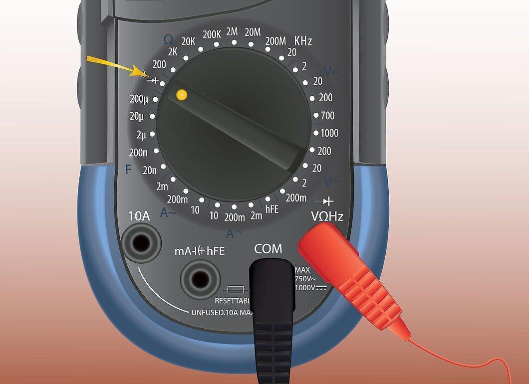
Use the dial to select the diode testing function. This may be represented by a symbol that looks like a diode, with an arrow pointing to a vertical line.
Step 3. Disconnect power from the circuit.
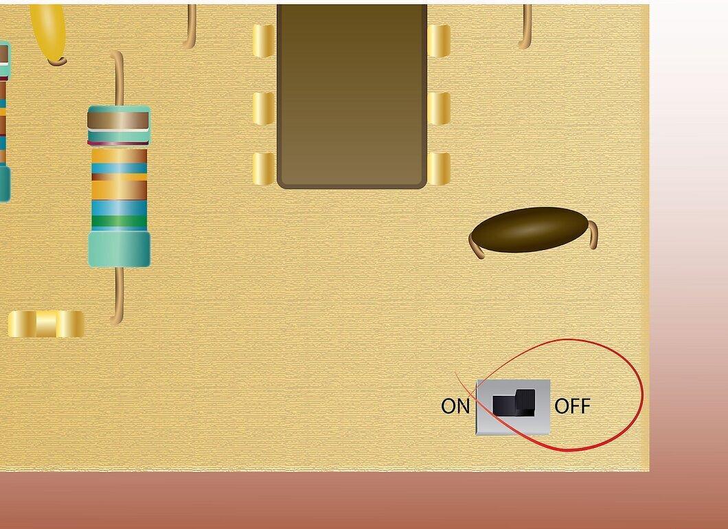
Step 4. Check the forward bias.
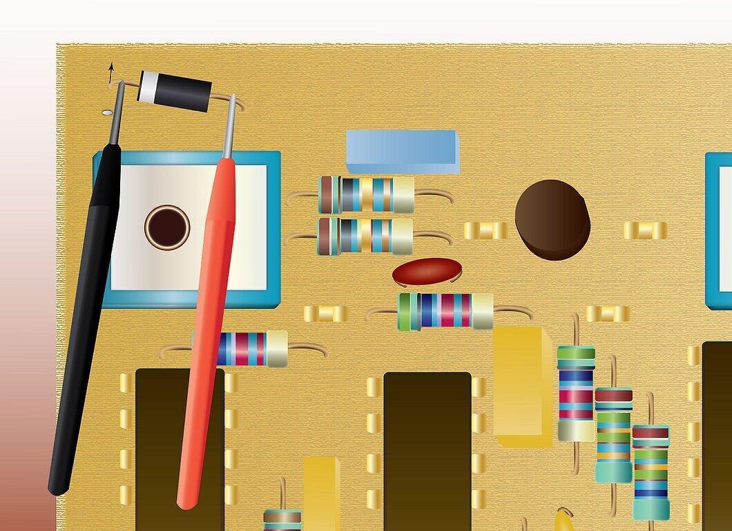
Check the forward bias. Place the red probe on the positive side of the diode and the black probe on the negative side. If you get a reading less than 1 but greater than 0, the forward bias is good.
Step 5. Swap the probes to check the reverse bias.

Swap the probes to check the reverse bias. If the display shows "OL" (overload), this indicates that the reverse bias is good.
Step 6. A reading of "OL" or 0 when testing forward bias and 0 when testing reverse bias indicates a faulty diode.
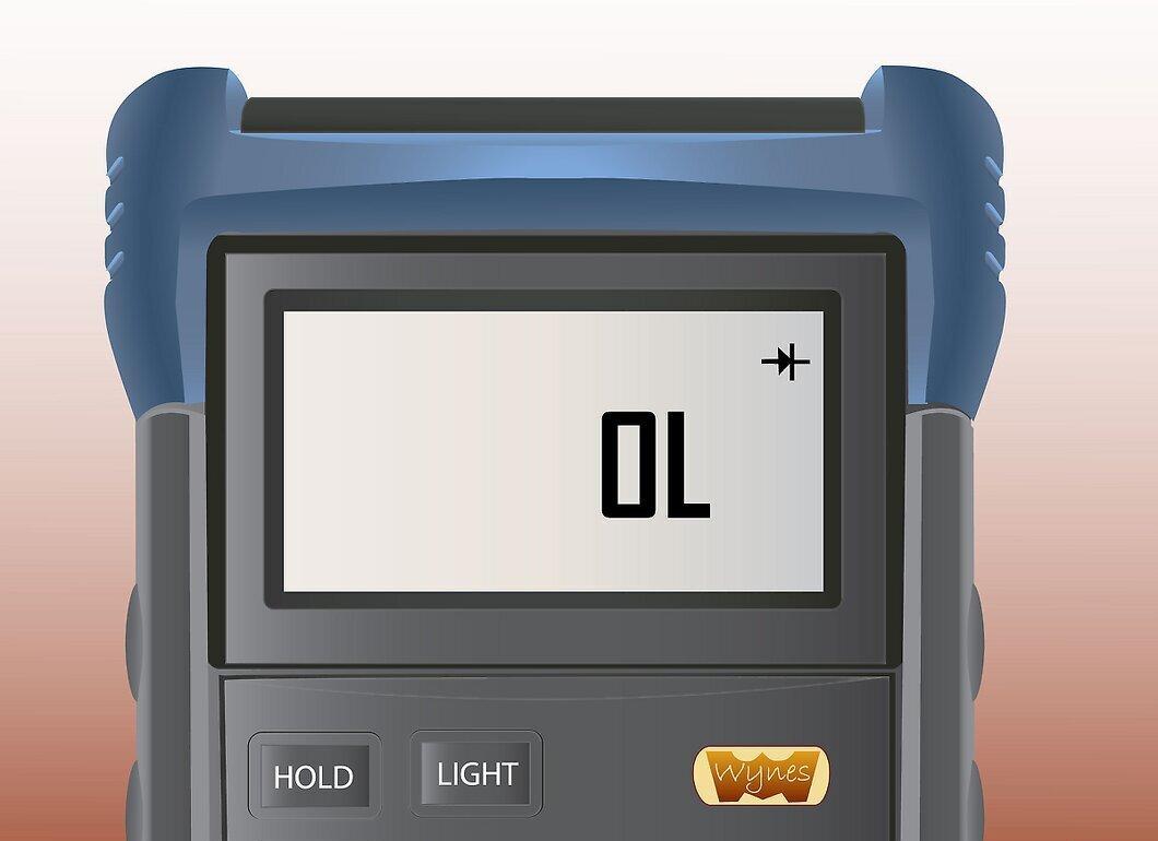
- Some multimeters will beep when readings are less than 1. This does not necessarily indicate a good diode, as a shorted diode will also trigger a beep.
Measuring Conductivity
Step 1. Insert the black probe into the common jack and the red probe into the jack used for measuring volts and ohms.
Step 2. Set the multimeter to the value used for testing diodes.
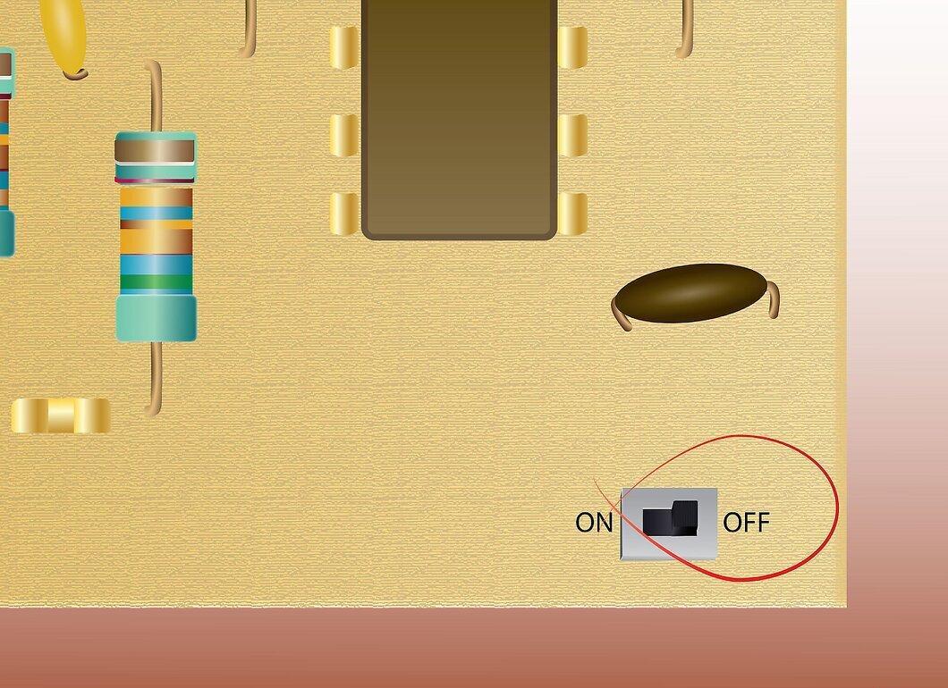
Step 3. Disconnect power from the circuit.
Step 4. Connect the probes on either side of the section of the circuit you are testing.
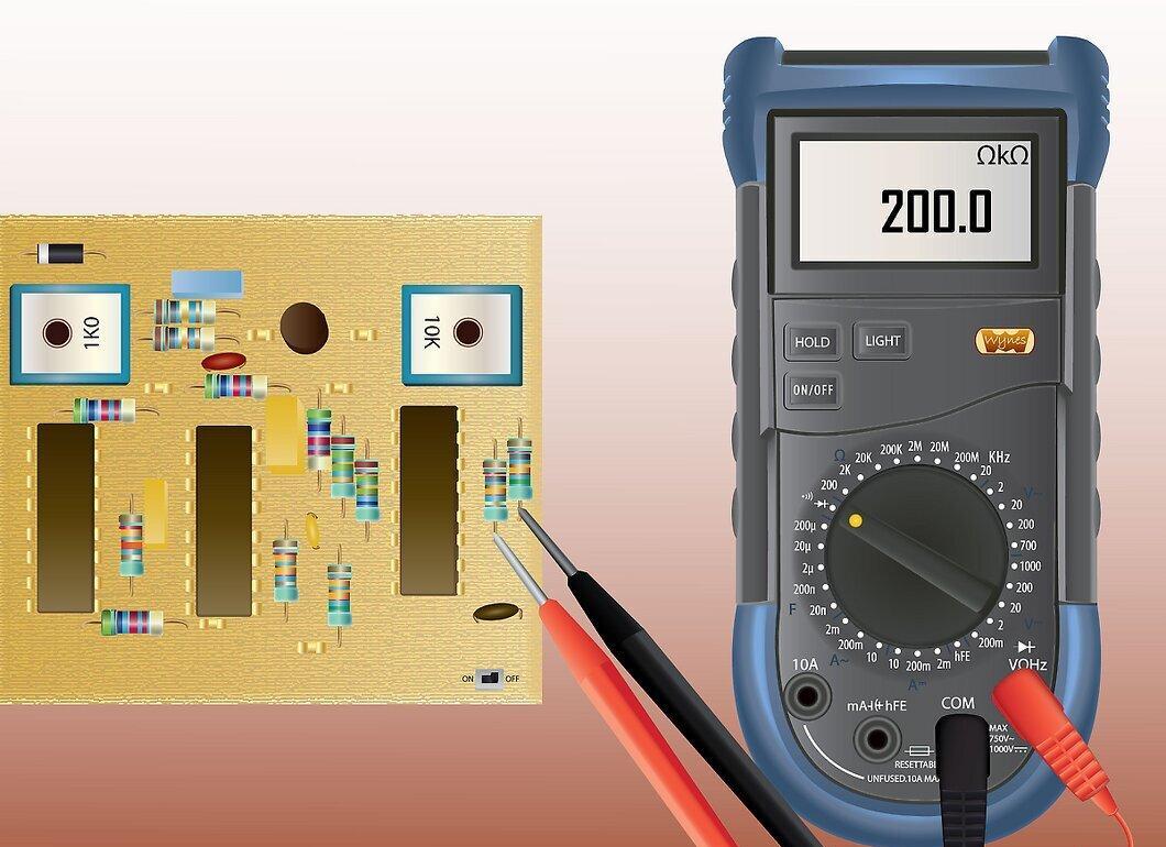
Connect the probes on either side of the section of the circuit you are testing. Polarity does not need to be observed. A reading of less than 210 ohms indicates good conductivity.