A voltmeter is one of the most useful tools for checking electrical circuits at home when used correctly. Before using a voltmeter for the first time, learn how to operate the device properly and test it on a low-voltage circuit, such as a household battery.
Setting Up the Device
Step 1. Set the device to measure voltage.
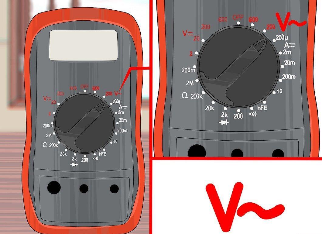
Set the device to measure voltage. Most voltage measuring devices are actually "multimeters" that can check several parameters of electrical current. If your device has a switch with multiple settings, set it as follows:
- To check AC voltage, set the switch to V~, ACV, or VAC. Household electrical systems are almost always AC.
- To check DC voltage, choose V–, V---, DCV, or VDC. Batteries and portable electronic devices typically use DC.
Step 2. Select a range higher than the maximum expected voltage.
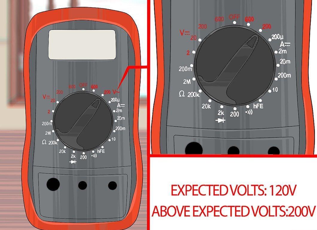
Select a range that is higher than the maximum expected voltage. Most voltmeters offer several options to choose from, allowing you to adjust the device's sensitivity for accurate readings and to avoid damaging the device. If your digital device does not allow you to select a range, it selects automatically — the device will determine the correct range itself. Otherwise, follow these instructions:
- Choose a setting "above" the maximum expected voltage. If you are unsure of the values to expect, choose the highest option available to avoid damaging the device.
- Household batteries typically indicate a voltage, usually 9V or lower.
- Car batteries provide about 12.6V when fully charged and the engine is off.
- Household outlets usually deliver 240 volts in most countries and 120 volts in the USA and some others.
- mV stands for millivolt (1/1000 V), and this unit of measurement sometimes indicates the minimum value in the device settings.
Step 3. Insert the probes.
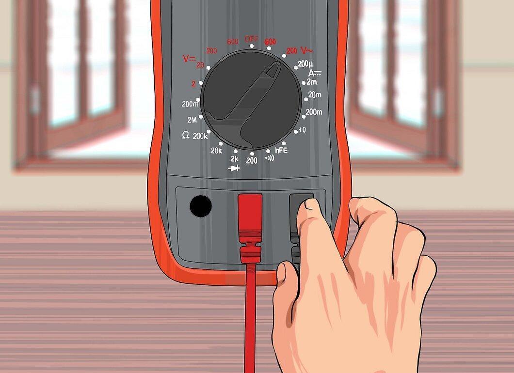
Insert the probes. The voltmeter should come equipped with one black and one red probe. Each has a metal tip at one end and a metal connector at the other end that plugs into the voltmeter. Connect the probes as follows:
- The black jack is usually connected to the hole marked "COM."
- When measuring voltage, plug the red jack into the hole marked V (among other symbols). If there is no V marking, choose the hole with the lowest number or the mA marking.
Measuring Voltage
Step 1. Hold the probes safely.
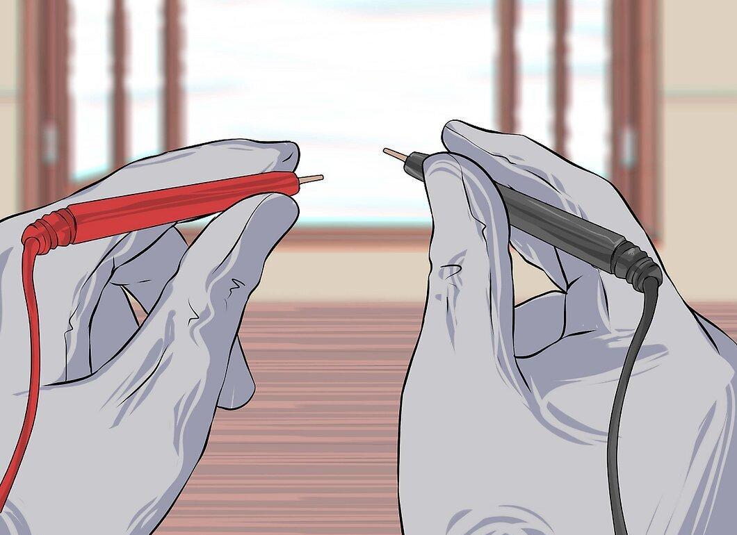
Hold the probes safely. Do not touch the metal tips when connecting them to the circuit. If the insulation looks worn or damaged, wear insulating gloves or get replacement parts.
- The two metal probes should never touch each other while measuring voltage, as this could cause a spark and short circuit.
Step 2. Place the black probe on one part of the current conductor.
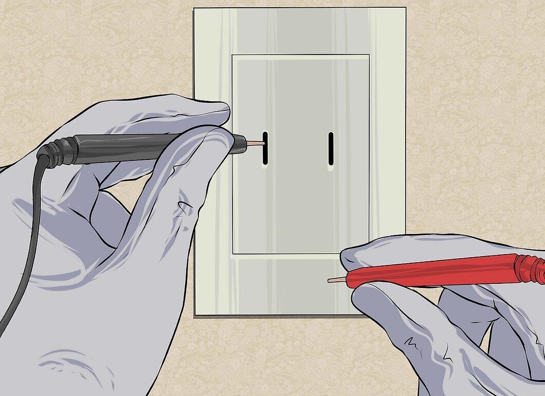
Place the black probe on one part of the current conductor. Measure voltage by placing the probes in parallel. In other words, you apply the probes to two points in a closed circuit where current flows between them.
- For batteries, place the black probe on the negative terminal.
- When measuring voltage at an outlet, place the black probe in the "neutral" hole, which in the USA is the larger vertical hole or the vertical hole on the left side.
- Whenever possible, secure the black probe before proceeding. Many black probes have a small plastic feature that allows you to lock the probe in the outlet.
Step 3. Touch the red test probe to another point in the circuit.
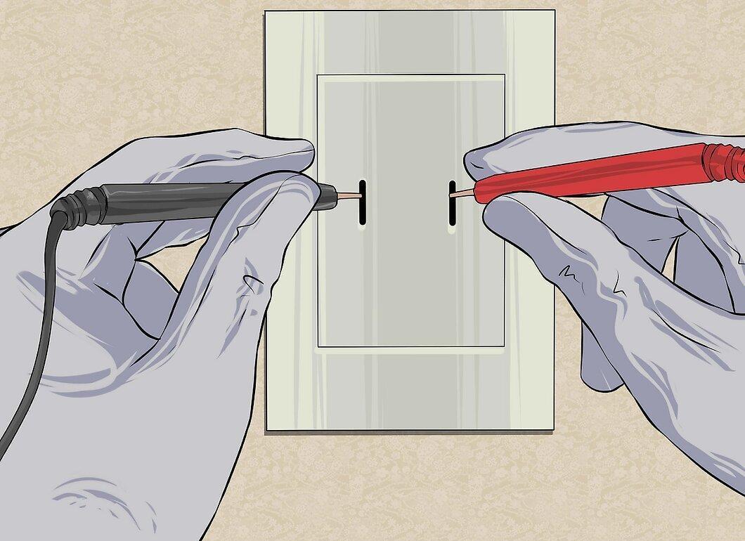
Touch the red test probe to another point in the circuit. This will close the parallel circuit and cause the measuring device to show the voltage.
- For batteries, touch the red probe to the positive terminal.
- When measuring voltage at an outlet, insert the red probe into the phase hole — in the USA, this is the smallest vertical hole or the vertical hole on the right side.
Step 4. Increase the allowable range if you receive an overload message.
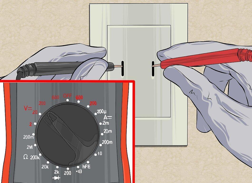
Increase the allowable range if you receive an overload message. Immediately increase the range on the voltmeter if you receive any of the following results:
- The digital display shows "OL," "overload," or "1."
- On an analog voltmeter, the needle jumps to the other end of the scale.
Step 5. Adjust the voltmeter if necessary.
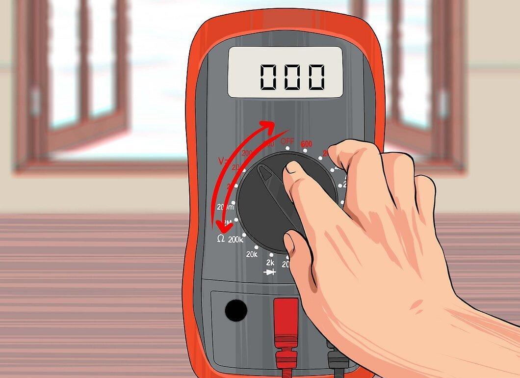
Adjust the voltmeter if necessary. You may need to adjust the settings of the digital voltmeter if the display shows 0V or nothing at all, or if the needle on the analog voltmeter barely moves. If there are still no readings, try the following in order:
- Ensure both probes are touching the circuit.
- If you’re measuring voltage in a DC circuit and getting no results, look for a small lever or switch on the device labeled DC+ and DC-, and move it to the other position. If your device does not have such an option, swap the black and red probes.
- Decrease the range by one unit. Repeat as necessary until you get a reading.
Step 6. Read the voltmeter's readings.
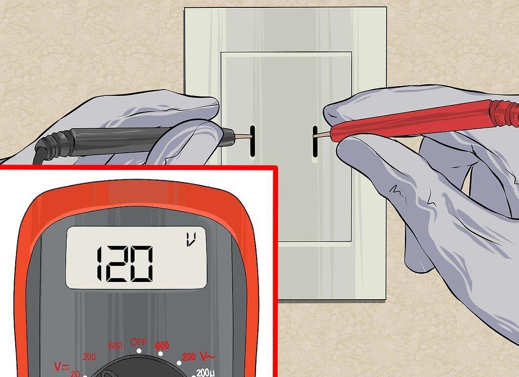
Read the voltmeter's readings. Digital voltmeters clearly display the voltage on an electronic screen. Analog voltmeters are a bit more complex to work with, but not too difficult once you understand the readings. Continue reading for instructions.
Reading the Analog Voltmeter's Readings
Step 1. Find the voltage scale at the end of the needle.
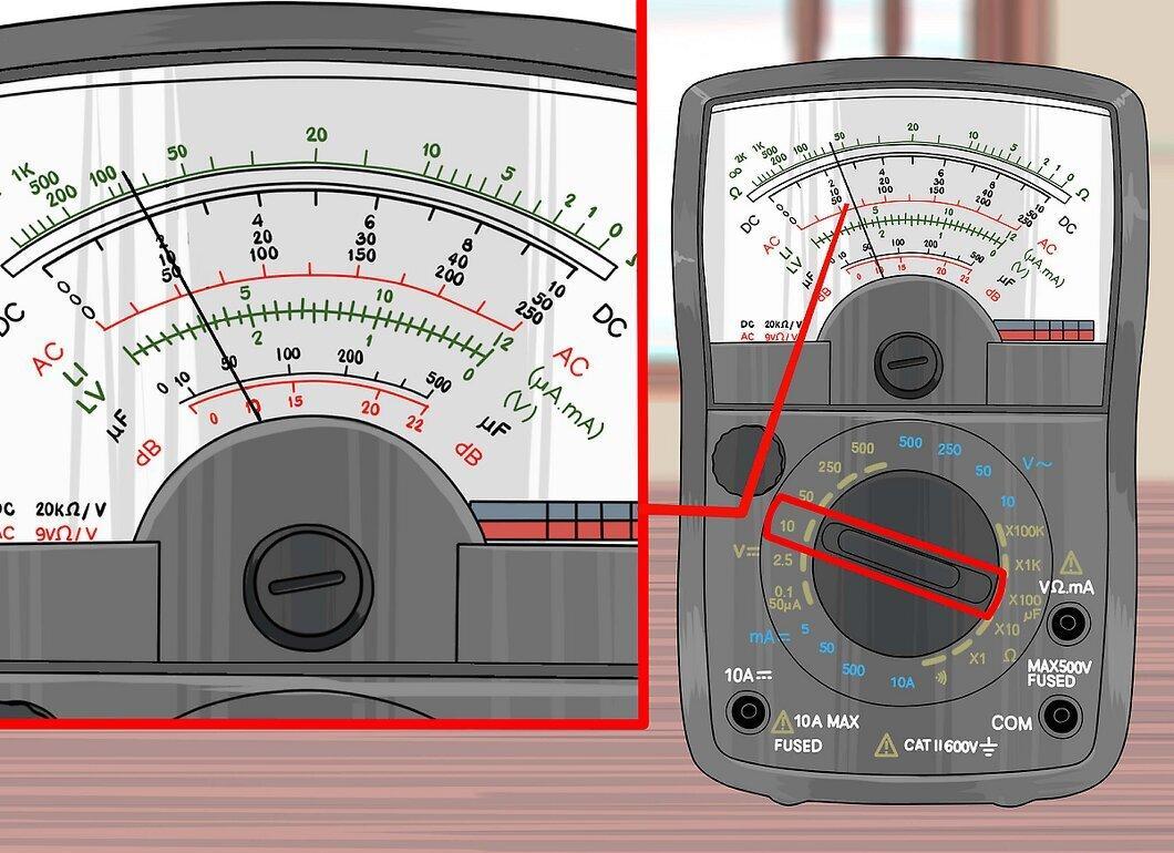
Find the voltage scale at the end of the needle. Select the reading that you set when you configured the voltmeter. If there is no exact match, calculate the reading based on the scale.
- For example, if the voltmeter is set to DC 10V, look for the DC scale marking with a maximum value of 10. If there is none, find the one with a maximum value of 50.
Step 2. Calculate the expected position of the needle based on adjacent numbers.
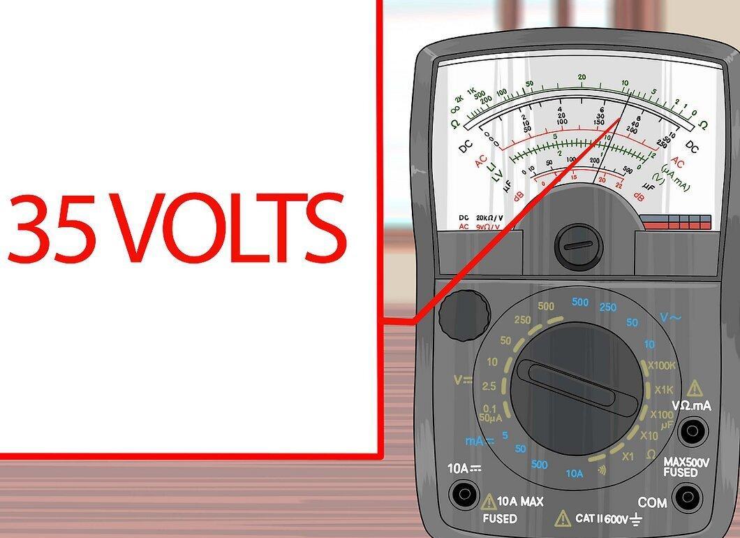
Calculate the expected position of the needle based on adjacent numbers. This is a linear scale, like a ruler.
- For example, if the needle points halfway between 30 and 40, the voltage is 35V.
Step 3. Divide the obtained reading if using a different scale.
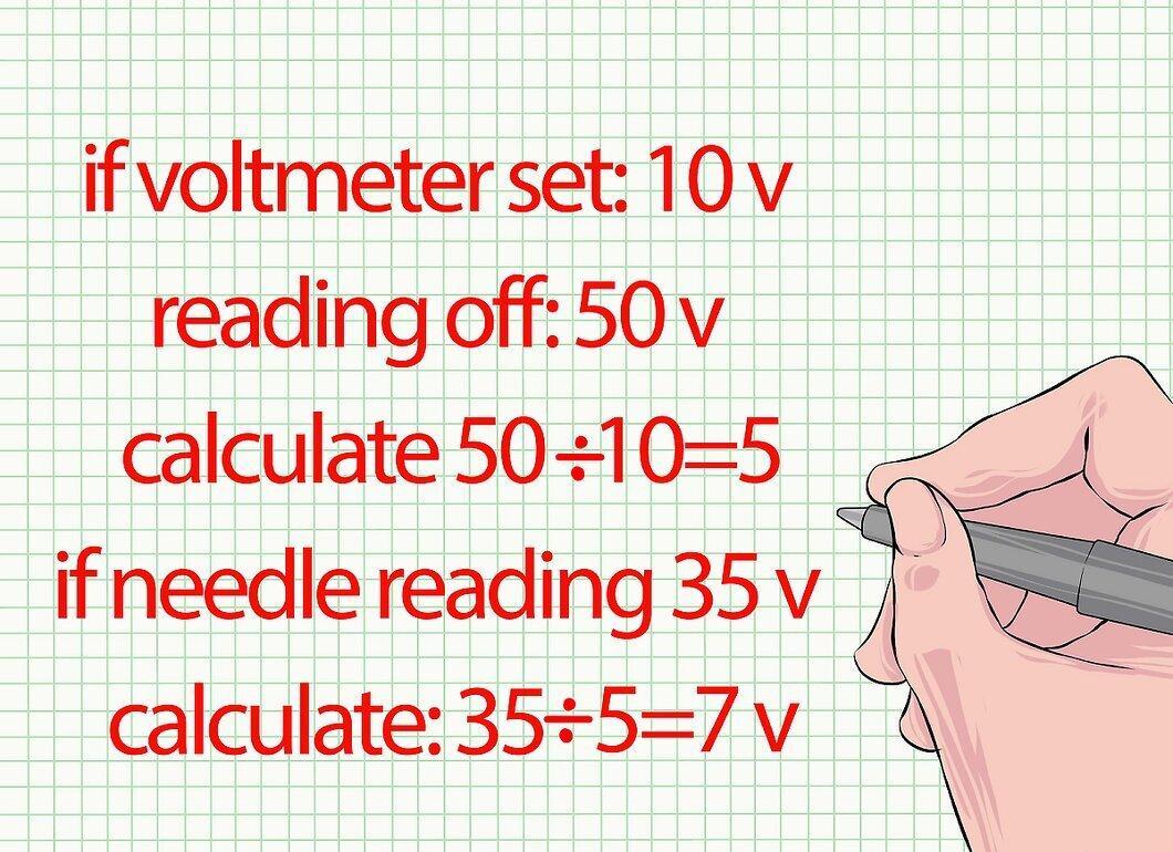
Divide the obtained reading if using a different scale. Skip this step if you are getting readings from a scale that exactly matches the settings of the voltmeter. Otherwise, make an adjustment by dividing the maximum value indicated on the scale by the settings of your voltmeter. Divide the number indicated by the needle by this result to find the actual voltage.
- For example, if the voltmeter is set to 10V but you are reading from the 50V scale, calculate: 50 ÷ 10 = 5. If the needle shows 35V, the actual voltage will be: 35 ÷ 5 = 7V.