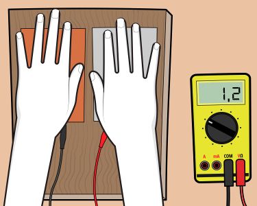
A multimeter is a versatile instrument used to measure both alternating and direct voltage, as well as resistance and the functionality of various electrical components. With it, you can easily determine whether there’s voltage in an electrical circuit. A multimeter can become your reliable assistant in solving many tasks. Start with the first section to learn how to use its basic functions, including measuring resistance (Ohms), voltage (Volts), and current (Amperes).
Getting to Know Your Multimeter
Step 1. Locate the Dial.
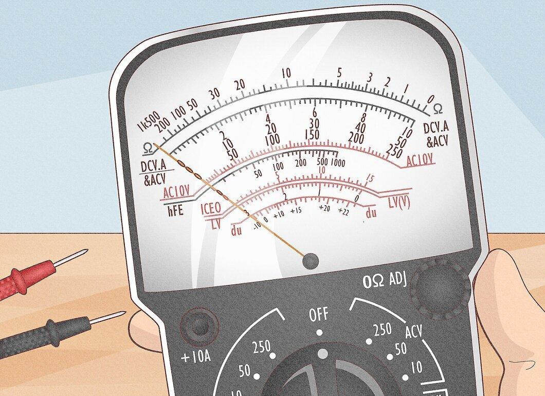
Take a look at the multimeter dial. It features a curved scale visible through a clear window, with a needle indicating values on that scale.
- The scales may vary in color and have different ranges of values, showing different levels of measurements.
- Some multimeter models have a mirrored scale that helps avoid "parallax" when reading. Align the needle with its reflection in the mirror before taking a reading. In the reflection, the needle will appear as a wide gray band between the red and black scales.
- Modern multimeters often come equipped with digital displays that show numerical values instead of an analog scale.
Step 2. Locate the Function Switch.
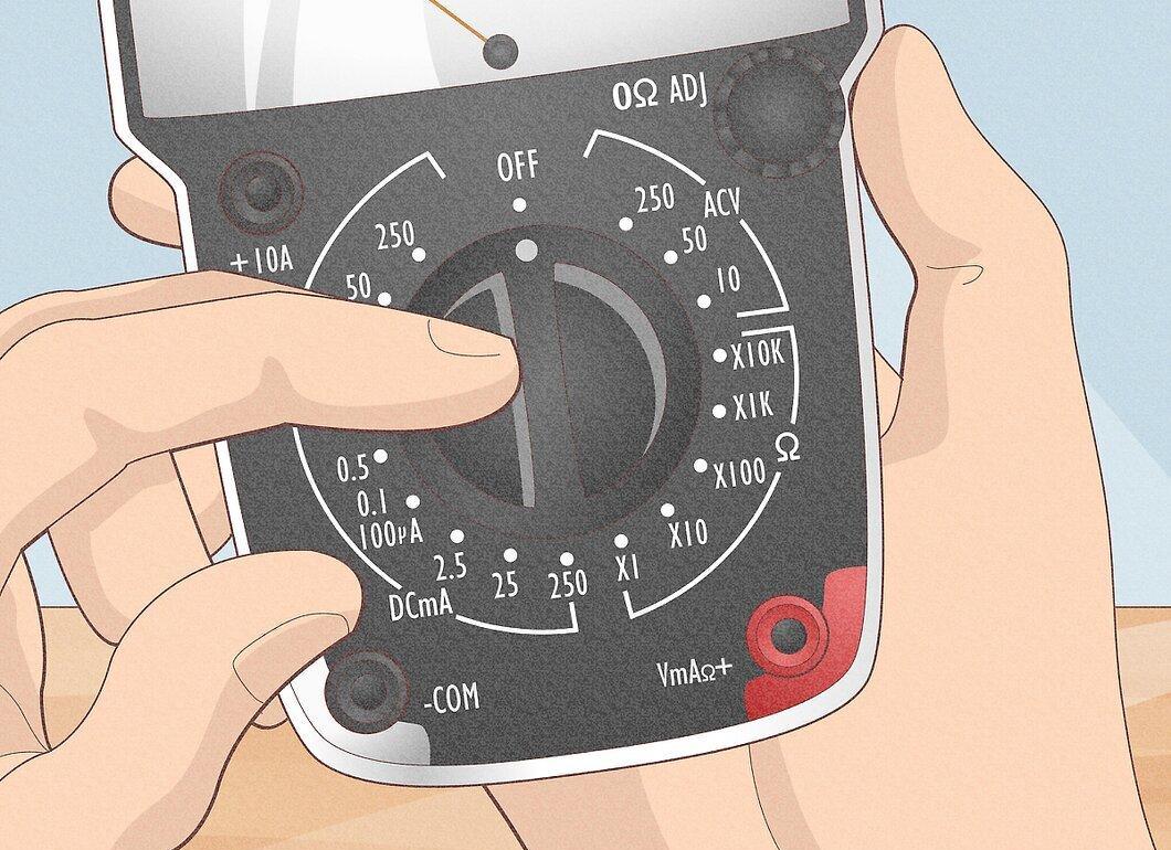
Take note of the function switch. It allows you to change measurement modes, such as voltage or resistance, and adjust ranges (x1, x10, etc.). Ensure that you set the measurement limits correctly to avoid damaging the device.
- Some multimeters have an "Off" position on this switch, while others have a separate button for turning it on. Remember to set the switch to "Off" when storing the device.
Step 3. Locate the Probe Jacks.
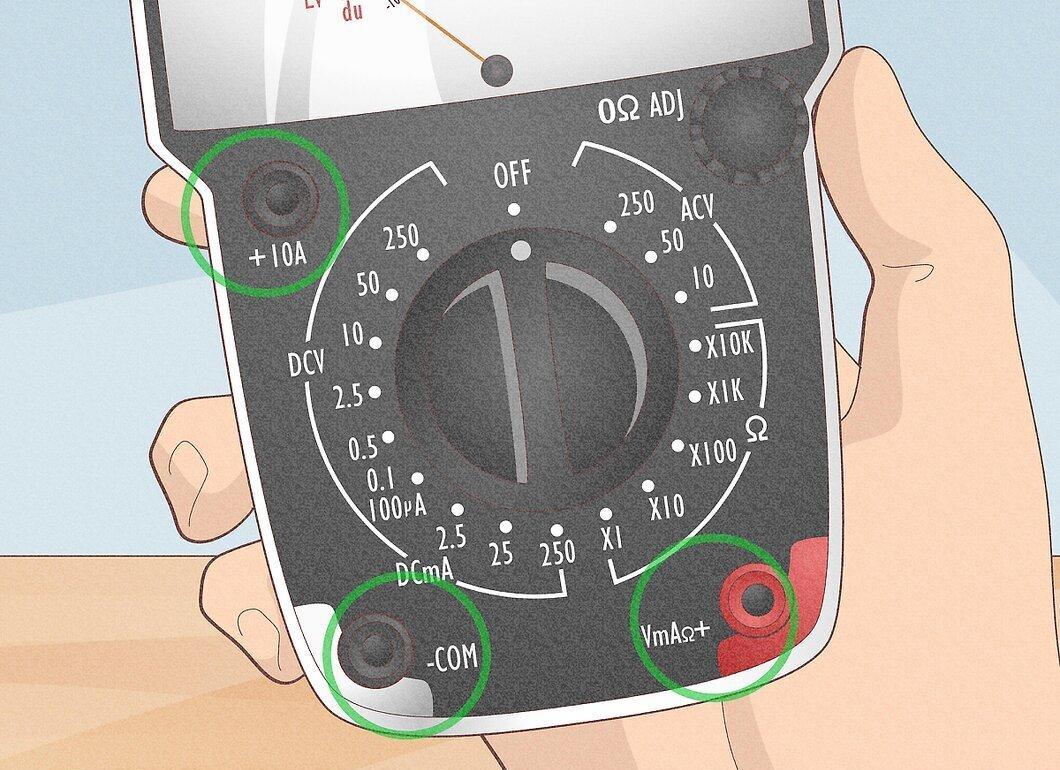
Notice the jacks for connecting the test probes. Most multimeters have several of these jacks.
- One is typically labeled "COM" or (-), intended for the black probe. It's used for most measurements.
- Other jacks may be labeled "V" (+) and the Omega symbol (shaped like a horseshoe) for measuring Volts and Ohms, respectively.
- The symbols “+” and “-“ indicate the polarity of the probes when measuring direct voltage. If the probes are connected correctly, the red wire will be positive relative to the black. This is useful to know if the circuit being tested is not marked.
- Some multimeters have additional jacks for measuring current or high voltage. It's important to connect the probes correctly and set the range on the switch, as well as select the type of measurement (Volts, Amps, Ohms). If in doubt, refer to the user manual.
Step 4. Locate the Test Leads.
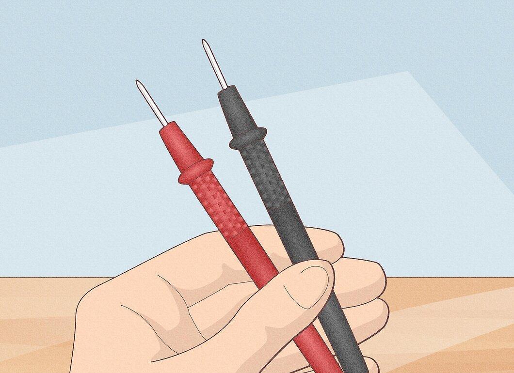
Check for the test leads. Typically, a multimeter comes with two leads: one black and one red. They are for connecting to the devices being tested.
Step 5. Locate the Battery and Fuse Compartment.
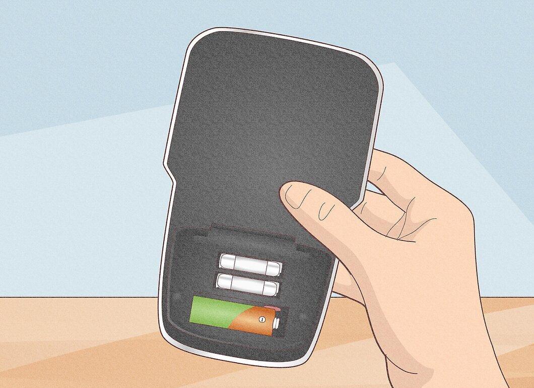
Notice the compartment for the battery and fuse. These are usually located at the bottom of the device, and sometimes on the side. In these compartments, you'll find the fuse (possibly a spare) and a battery that powers resistance measurements.
- The multimeter may use several batteries of different sizes. The fuse is necessary to protect the device during measurements. There may occasionally be multiple fuses. Fully charged batteries or new batteries are essential for accurate resistance readings.
Step 6. Locate the Zero Adjustment Knob.
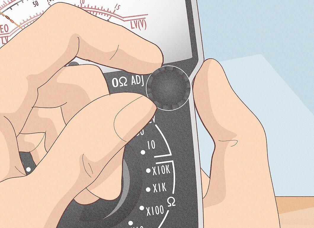
Take note of the zero adjustment knob. This is usually a small button near the dial, labeled "Ohms Adjust", "0 Adj", or something similar. It is used only in resistance measurement mode when the probes are shorted together.
- Turn the knob slowly to set the needle as close to zero as possible on the Ohm scale. If new batteries are installed, this should be straightforward; if the needle doesn’t reach zero, the batteries may be low and need replacement.
Measuring Resistance
Step 1. Set the Multimeter to Resistance Measurement Mode.
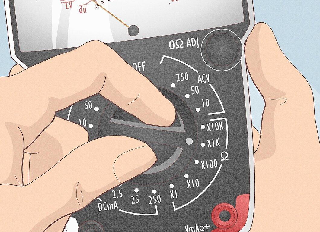
Switch the multimeter to the resistance measurement mode. If the device has a separate switch, turn it on. Remember that you cannot check a circuit for a short circuit while measuring resistance, as resistance and conductance are opposing values. Low resistance means high conductance, and vice versa. Considering this, you can draw conclusions about conductance based on resistance values.
- Find the Ohm scale on the dial. It is usually located at the top and has a maximum value on the left ("∞" or sideways "8"), decreasing gradually to 0 on the right. This is opposite to other scales, where minimum values are on the left and maximum on the right.
Step 2. Watch the Needle.
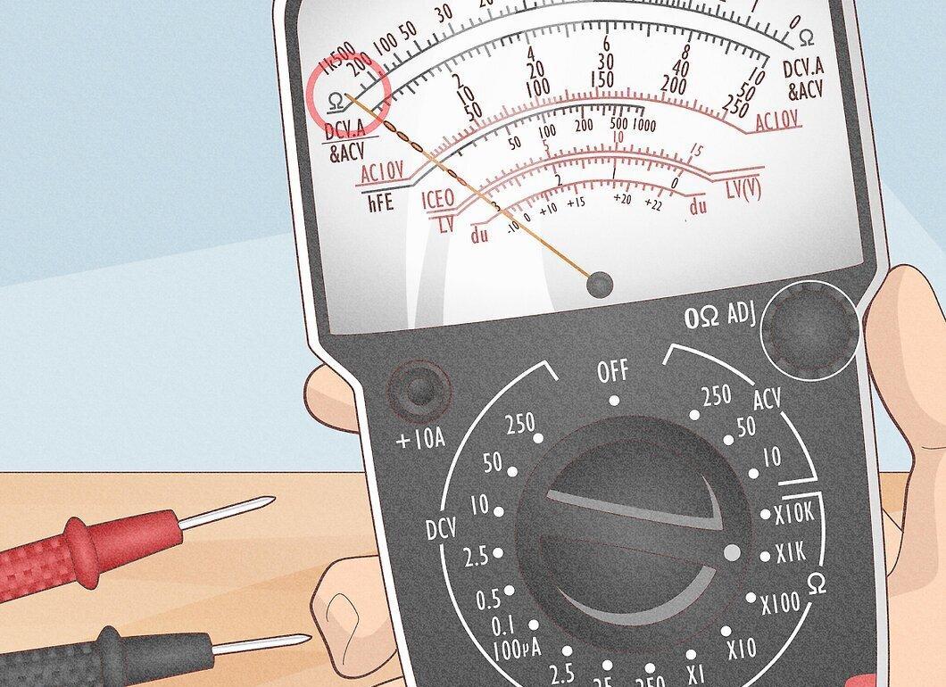
Observe the multimeter's needle. If it deflects fully to the left, this indicates infinite resistance or a "circuit break." In this case, you can confidently say there is no conductance, or there is a break between the black and red probes.
Step 3. Connect the Probes.
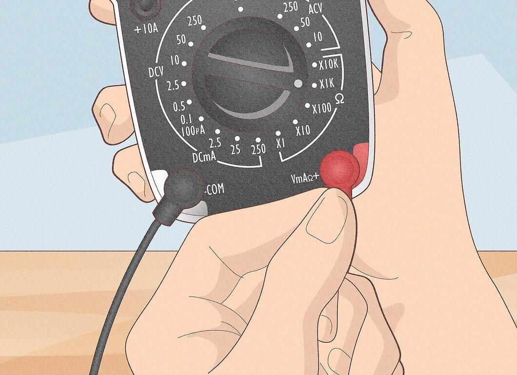
Connect the test probes. Insert the black probe into the jack labeled "Common" or "-", then connect the red probe to the jack marked with the Omega symbol (Ohm symbol) or the letter "R" next to it.
- Set the range (if available) to R x 100.
Step 4. Short the Probes Together.
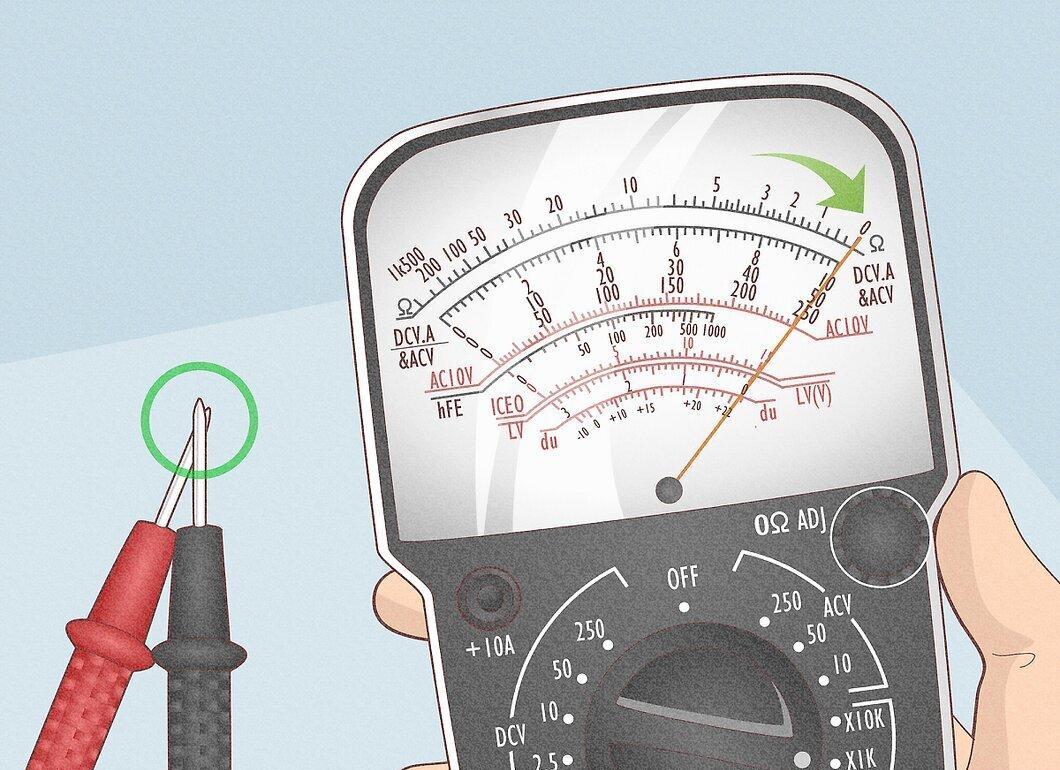
Short the probes together. The needle should deflect fully to the right. Find the "Zero Adjust" setting and turn the knob so that the needle settles on "0" (or as close to "0" as possible).
- Remember, this position corresponds to "short circuit" or "zero Ohms" in the R x 100 range.
- It is always necessary to calibrate the multimeter to "zero" when changing the resistance measurement range; otherwise, you will get incorrect values.
- If the needle does not reach zero, this may indicate a low battery. Recalibrate after replacing it.
Step 5. Measure the Resistance of a Light Bulb.
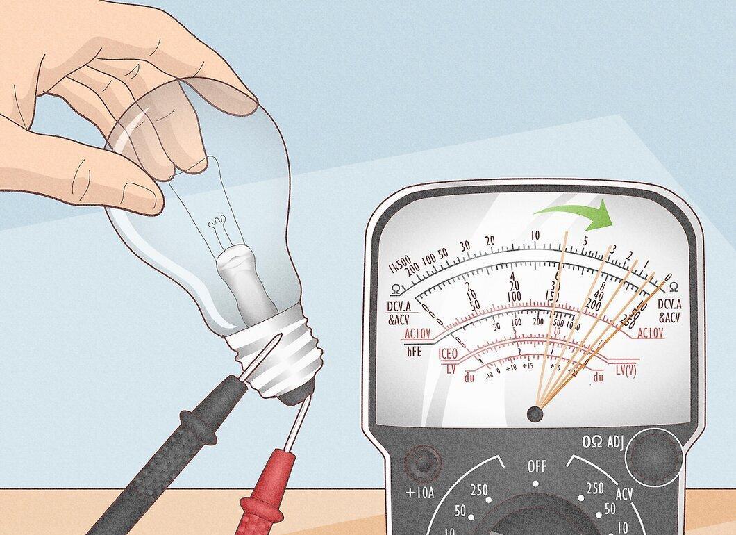
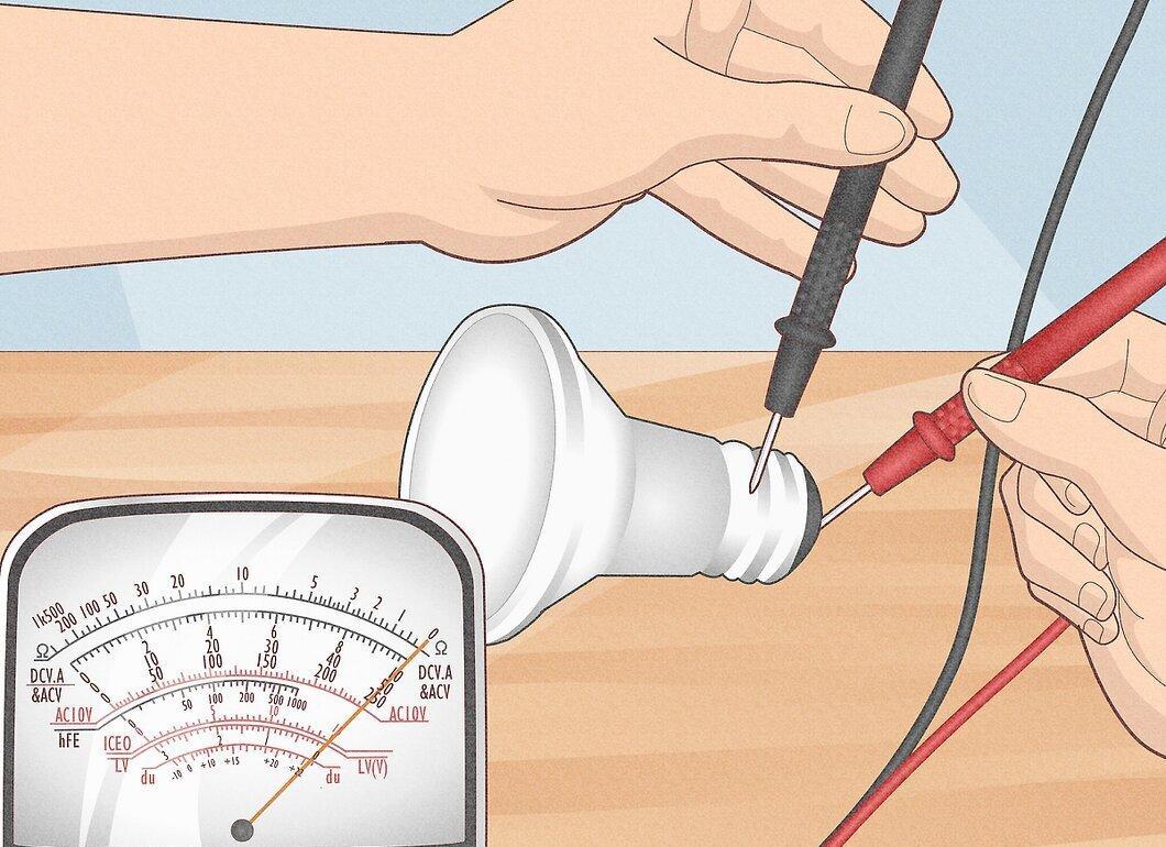
Locate the two contacts on the light bulb. One is the threaded base, and the other is the center of the bottom.
- Ask an assistant to hold the bulb by the glass.
- Press the black probe against the threaded base and the red one against the center.
- Watch the needle move from the left side of the dial towards "0" on the right.
Step 6. Try Different Ranges.
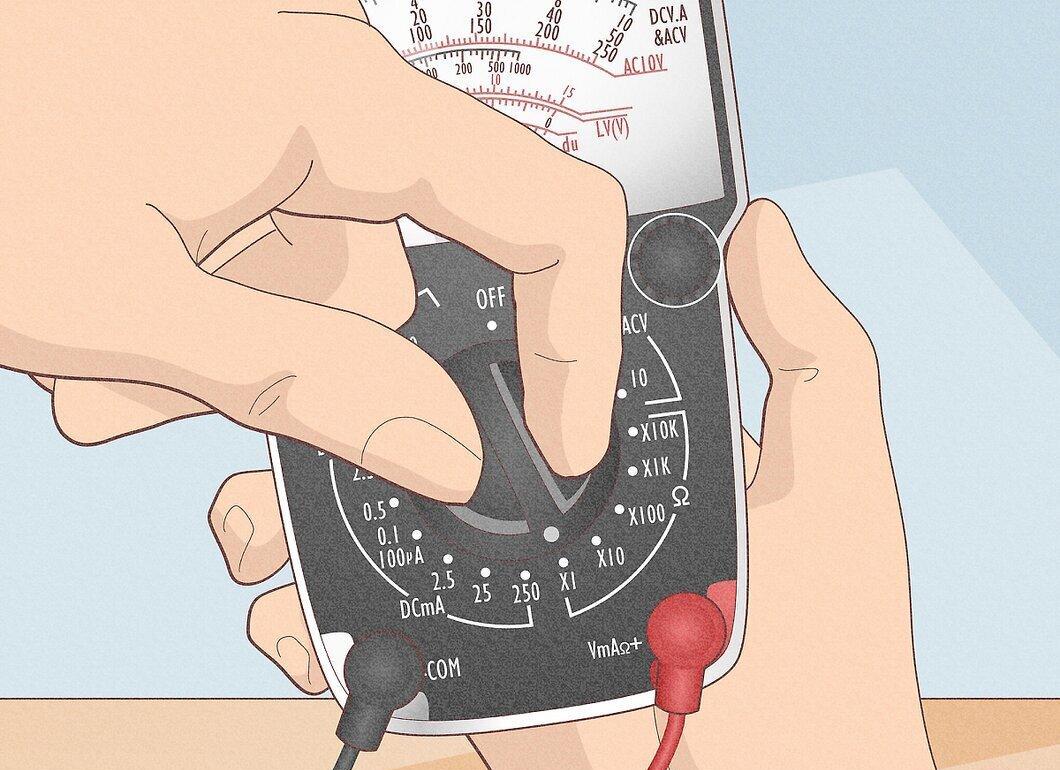
Change the range to R x 1. Perform the zero setup for this range and repeat the previous steps. The needle should not deflect as far to the right as before. This happens because each value on the scale now corresponds to the actual resistance without a multiplier.
- In the previous step, each value on the dial was 100 times larger. For example, 150 was displayed as 15,000. Now 150 is just 150. If the range of R x 10 were chosen, then 150 would be 1500. Choosing the correct range is critical for measurement accuracy.
- Note that the resistance measurement scale is not linear like others. Reading values on the left side of the scale can be more challenging than on the right. For instance, a value of 5 Ohms on the R x 100 range may look like 0. It’s easier to see this value on the R x 1 range. Therefore, when testing resistances, it’s important to select a range that allows readings to be taken in the center of the scale, rather than at its edges.
Step 7. Check Resistance Between Your Hands.
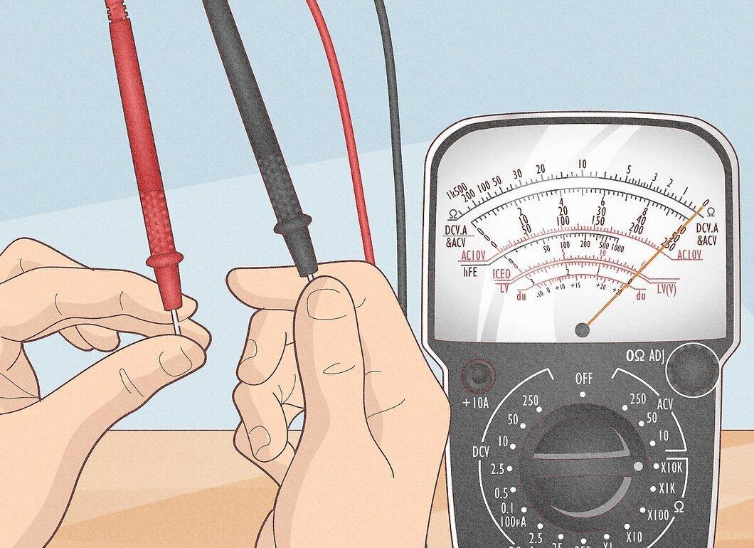
Set the multimeter to the highest range, then calibrate to zero.
- Hold the probes loosely in your hands and take a reading. If you squeeze both probes, you will notice that the resistance decreases.
- Wet your hands, then squeeze the probes again. Your resistance will become even lower.
Step 8. Ensure Accurate Measurements.
It is essential that the probes do not touch anything other than the device being tested. If the circuit has a break, it will not show infinite resistance during measurements if your fingers are touching the probes, creating an alternative path for the current.
- If you are testing fuses in old glass bodies, the multimeter may show low resistance values if the fuse is resting on a metal surface. This means you will see the resistance of the metal, not the fuse, which could lead to incorrect conclusions.
Measuring Voltage
Step 1. Set the Multimeter to the Maximum Range for AC Voltage if the Voltage Value is Unknown.
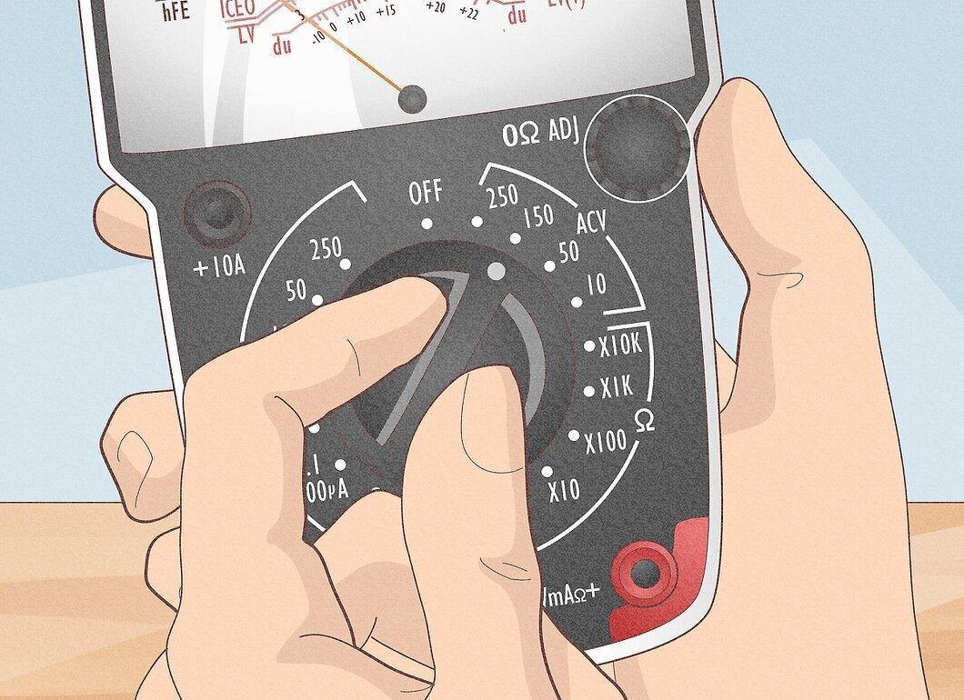
Set the multimeter to the maximum range for measuring AC voltage if you are unsure of the value. This is done to protect the multimeter from potential damage due to high voltage.
- If the multimeter is set to a range of up to 50 volts, and the electrical outlet (in Russia) is 220 volts, this will damage the device. Start at the highest range and gradually decrease it to a suitable one.
Step 2. Connect the Probes.
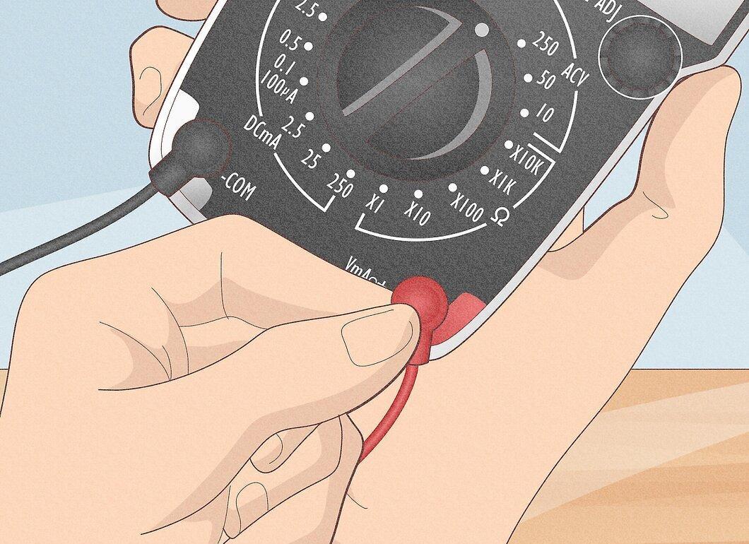
Insert the black probe into the "COM" or "-" jack, and the red probe into "V" or "+".
Step 3. Find the Voltage Scale.

Pay attention to the voltage scale. It may have different maximum values. The range you choose determines which scale you should read the values from.
- The maximum value of the scale should match the selected range. The voltage scales, unlike the resistance scale, are linear, which makes reading values more accurate across the entire length of the scale. For example, it’s easier to see a value of 24 Volts on the 50 Volt scale than on the 250 Volt scale, where it may fall between 20 and 30 Volts.
Step 4. Check the Voltage in the Outlet.
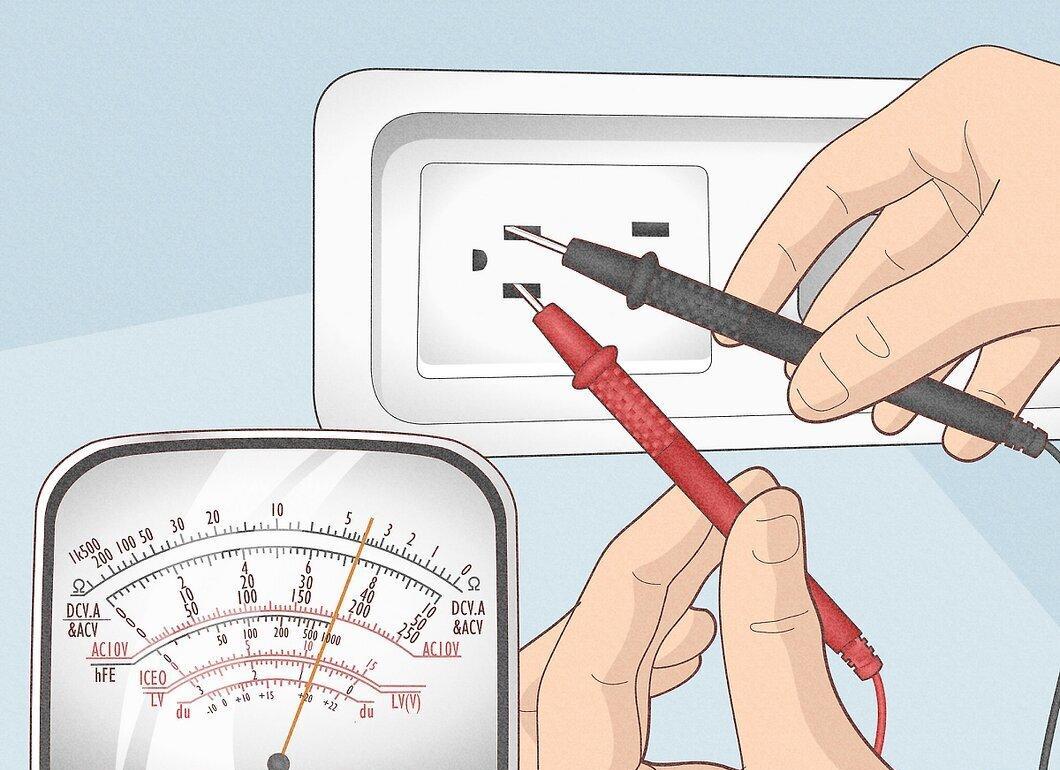
Insert the black probe into one hole of the outlet.
- Insert the red probe into the other hole. Expect the multimeter to show a voltage of around 120 or 220 Volts (depending on the country).
Step 5. Remove the Probes from the Outlet.
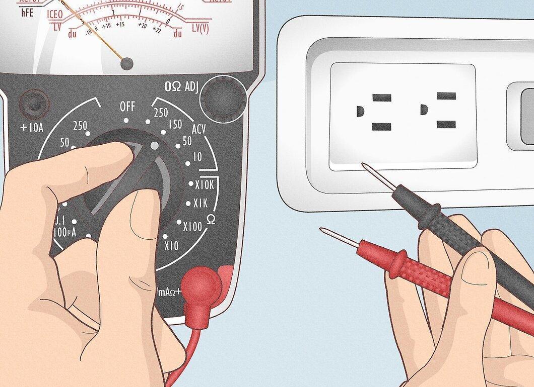
After taking the measurement, switch the dial to a lower range, still exceeding the voltage in the outlet (120 or 240 Volts).
Step 6. Connect the Probes Again.
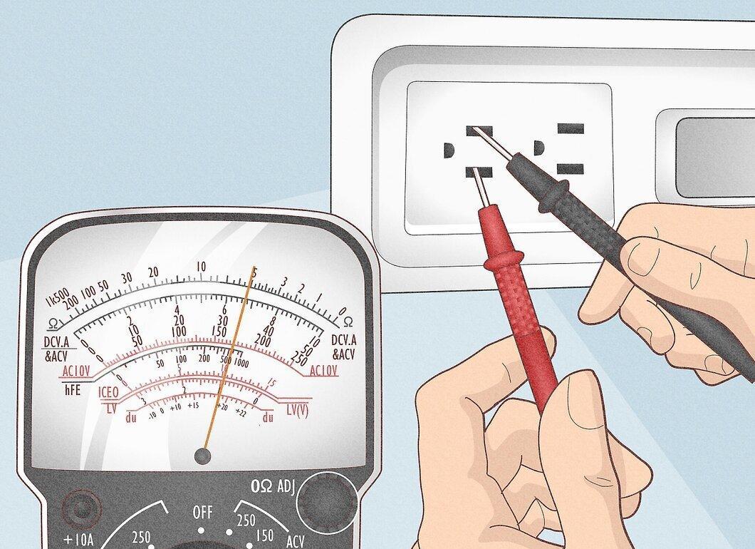
Insert the probes as you did before. Now the multimeter should show a voltage reading between 110 and 125 Volts (in the USA) or 220-240 Volts (in Russia). It’s important to choose the correct range to obtain accurate values.
- If the needle does not deflect, you may have selected the DC mode instead of AC. These modes are incompatible. Be sure the mode is set correctly. If it is set incorrectly, you might mistakenly believe there is no voltage, which can be dangerous.
- Always check both modes if the needle does not deflect. Set the multimeter to AC mode and try again.
Step 7. Avoid Holding Both Probes Simultaneously.
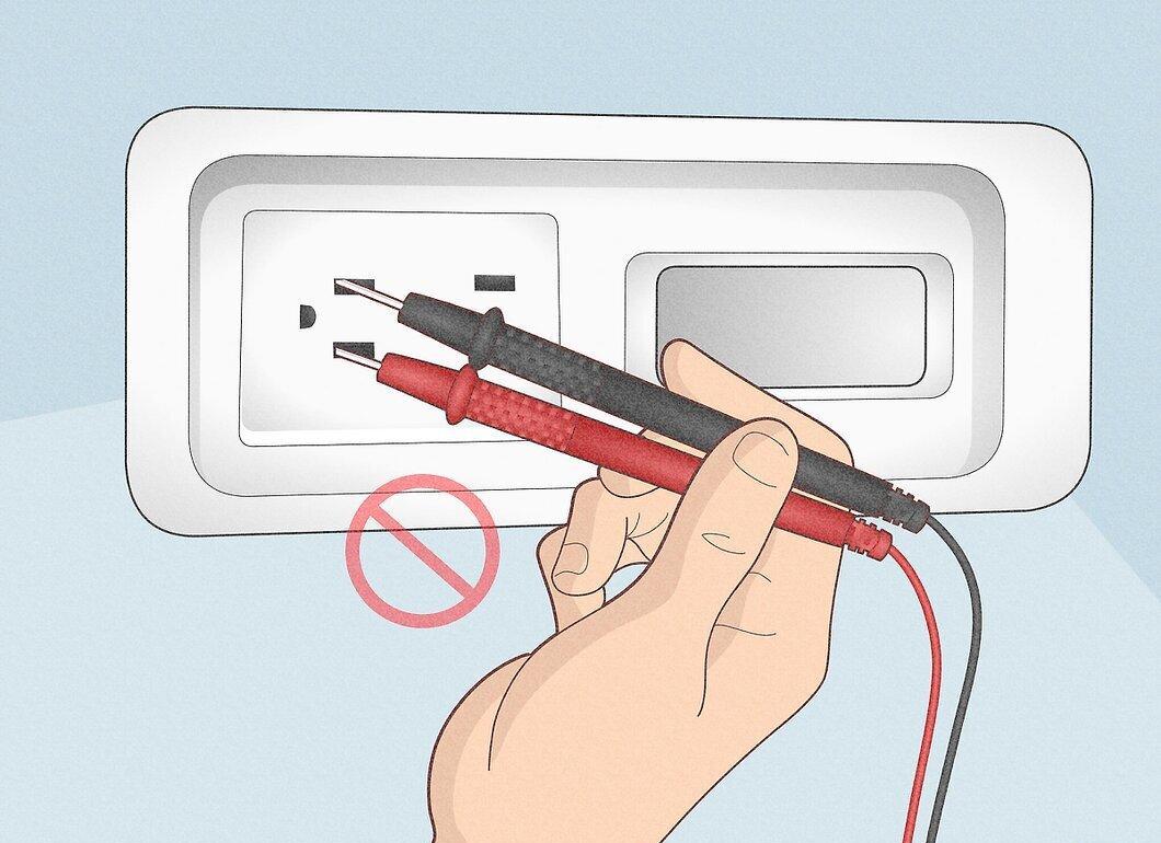
Try to avoid holding both probes at the same time. Whenever possible, connect at least one probe in a way that you don’t need to hold it while taking measurements. Some multimeters have clips that help with this. Reducing contact with electrical circuits lowers the risk of injury.
Measuring Current
Step 1. First, Measure the Voltage.
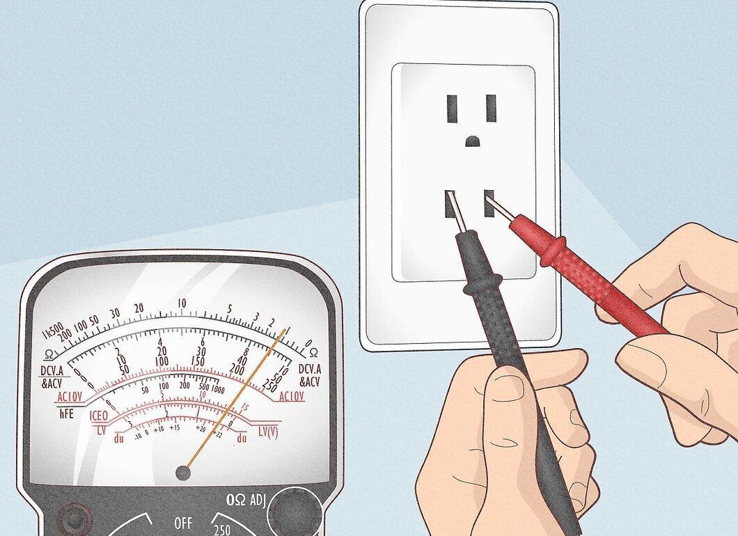
Start by determining whether the circuit is AC or DC by measuring the voltage in it, as described in the previous steps.
Step 2. Set the Range Switch to the Maximum Value for AC or DC Current.
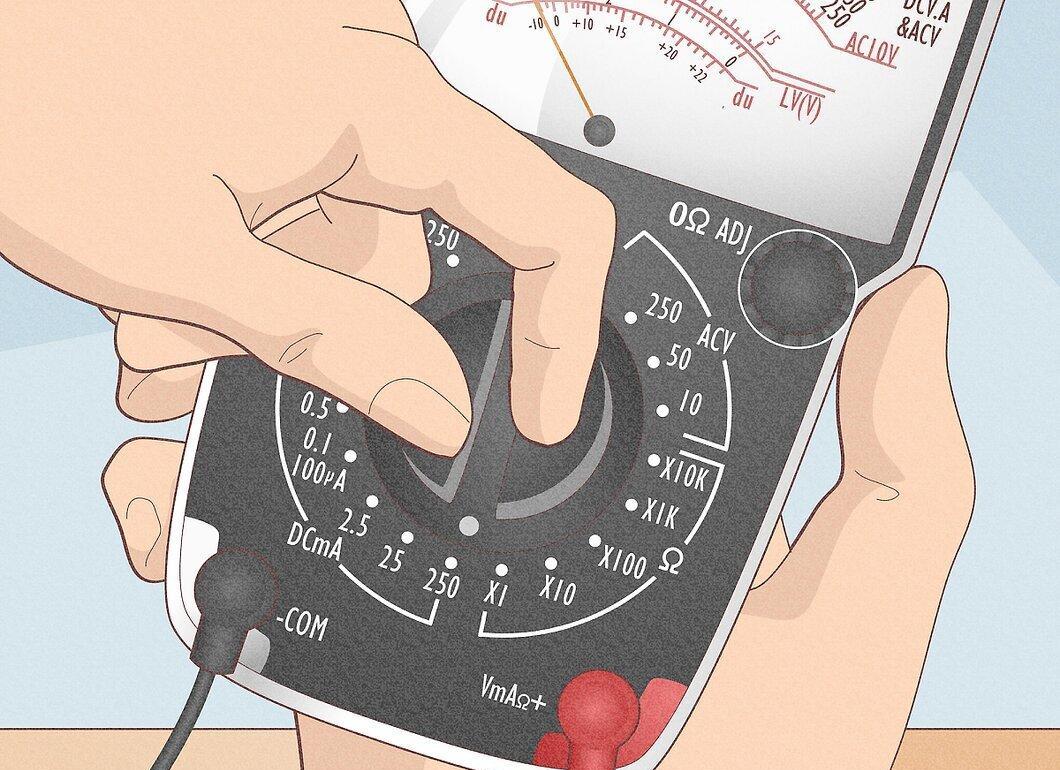
Switch the range to the maximum value for either AC or DC current. If the circuit being tested is AC and the multimeter is set to measure DC only, stop the measurement. Ensure the multimeter can measure in the same mode as the voltage in the circuit; otherwise, it will read "0".
- Keep in mind that most multimeters can only measure very small currents, in the microamp (µA) and milliamp (mA) range. 1 µA equals 0.000001 Amperes, and 1 mA equals 0.001 Amperes. These values are found only in low-power electronic circuits and are thousands (or even millions) of times smaller than currents typically used in household applications.
- For reference, a standard 100 W/120 V light bulb (in the USA) draws a current of 0.833 Amperes. Attempting to measure such a current could damage the multimeter.
Step 3. Use a Clamp Meter.
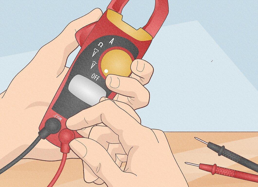
A clamp meter is ideal for measuring the current flowing through a 4700 Ohm resistor at 9 Volts DC.
- Insert the black probe into "COM" or "-", and the red probe into "A".
- Disconnect the power in the circuit.
- Break the circuit you need to test (unsolder one wire from the resistor). Connect the multimeter in series so that it closes the circuit. The ammeter should not be connected in parallel, or it will be damaged (this is how a voltmeter is connected).
- Observe the polarity. Current flows from positive to negative. Set the range to the maximum value.
- Turn the power back on in the circuit and gradually switch the multimeter range down to see more accurate readings. Do not exceed the allowable range, or the multimeter may be damaged. For example, a current value of around 2 mA will be displayed as I = V / R = (9 Volts) / (4700 Ohms) = 0.00191 A or 1.91 mA.
Step 4. Be Cautious with High-Voltage Capacitors.
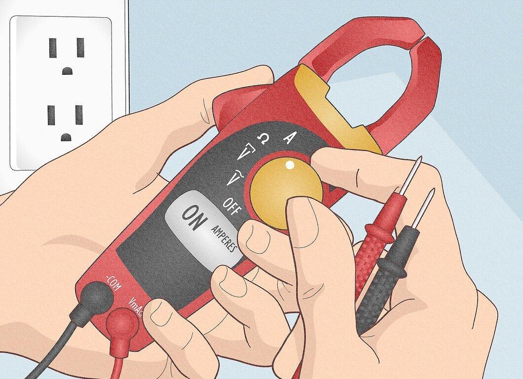
Be cautious of high-voltage capacitors, which are often used in power supply filters, and other components that may cause current spikes when the circuit is turned on. Even if the operating current is low and within the multimeter fuse's allowable range, a current spike may be significantly higher than normal, as discharged capacitors can create almost a short circuit in the circuit when powered on. The fuse is likely to blow if the current spike exceeds the rated current of the fuse. Always choose a higher measurement range for current in such circuits to protect the multimeter.